What is Power factor ? Easiest Explanation
What is Power factor ? Easiest Explanation https://www.theelectricalguy.in/wp-content/uploads/2020/06/01-1024x576.jpg 1024 576 Gaurav Joshi https://secure.gravatar.com/avatar/f6a3006f3f7233a71d79d0e705c167ae12516870e5239627478665ae377435b3?s=96&d=mm&r=gI have an induction motor whose power factor is 0.7. But I really don’t know what that means. What is the exact meaning of power factor & what 0.7 indicates?
These type questions are knocking many minds. But you don’t have to worry anymore, because by the end of this video the concept of power factor will be clyster clear to you. So, let’s start!
Before moving on in this tutorials, I would strongly recommend you to watch my video on Active, reactive & apparent power first, as it will help you to understand the concept of power factor more clearly.
Power in purely resistive circuit
Consider a 60 ohms resistive load which is connected to a 230volts AC supply.
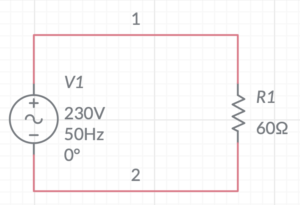
To find out current flowing through this system we need to divide voltage by resistance, as per the ohms law.

 Amps
Amps
So, 3.83 Amps RMS, is the current flowing through the system. As it is a resistive circuit, current & voltage are in phase with each other. In phase means, current & voltage reaches their zero value, and peak value at the same time. Now, if I have to draw the power waveform of this circuit, it will look like this.
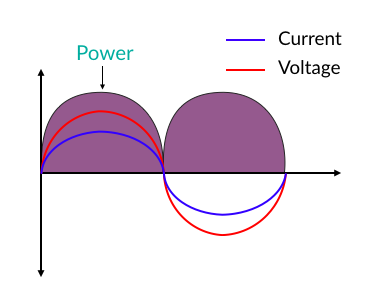
Here we can notice, the power is always positive! Which means that, whatever power is taken by the system is being utilised. And hence, no power is wasted.

 watts
watts
Circuit is taking 880.9 watts of power. If the source is generator, it would only take mechanical energy which is required to produce 880.9 watts of energy. And we can say that the power taken by this circuit is Active power!
Power in purely inductive/capacitive circuit
Let’s take a second case. Let’s say, now, I have replaced the 60 ohms resistive load by a 160 mH inductor.
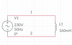
To calculate current flowing through this circuit we first need to calculate the reactance of the inductor. Let’s do it,
XL = 2πFL
XL = 2π X 50 X 160 X 10^-3
XL = 50.24 ohms
So, impedance is equal to 50.24 ohms. Now, we can calculate the current.

 Amps
Amps
So, the current flowing through the system is 4.57 amps RMS. As, this is purely an inductive circuit, current is out of phase with voltage by 90 deg. To get the power of this circuit we will multiply voltage & current at every instance, and the resulting power waveform in such circuit will look like this.
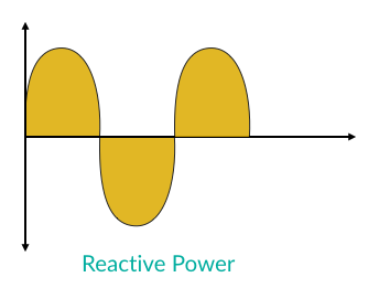
As you can see, power is alternating equally between the positive & negative cycle. This means that some amount of power is taken by the circuit & the same amount is returned to source. Therefore, ideally, no net power is utilised! If the source is a generator, it would take no net mechanical energy to turn the shaft, as no power is being utilised by the load. But, as there is a voltage drop across the inductor and also the system is taking current, it gives a deceptive statement that the circuit do consume power. And that power is called as Reactive power!
The same thing will happen if we replace the pure inductive load by a pure capacitive load.
Power in mixed circuit
The interesting part starts in the third case! Now, I’ll add a 60-ohm resistor with 160mH inductor.
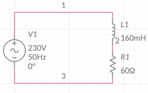
To calculate the current flowing through this circuit we need to calculate the impedance of the circuit first.

 Ohms
Ohms

 Amps
Amps
The current flowing in this circuit is 2.93 amps RMS. As we know, purely inductive circuit, ideally, will not consume any amount of power. But we must not forget about the resistor in this circuit. It will definitely consume power. Current & Voltage will be out of phase as some amount of load is inductive. If we draw the power waveform of this circuit, it’ll look like this.
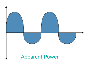
We’ll find that positive power is more than the negative power. In previous case of purely inductive circuit, we have seen that power waveform is equally divided in the positive & negative section. And hence the net power is zero! However, in circuit which is mixed with resistance & reactance like the one shown above, power will still alternate between positive & negative but, the amount in positive will be more than the negative. In simple words, such mixed circuits will consume more power than it returns back. So, the power in such circuit is not purely active or reactive, it is the combination of both, and hence it is called as Apparent power!
Now let’s calculate all the three powers i.e. active, reactive & apparent power in this circuit.
- Active Power =
 watts
watts
- Reactive Power =
 VAR
VAR
- Apparent Power =
 VA
VA
We can relate these three powers by drawing a triangle which is called as power triangle.
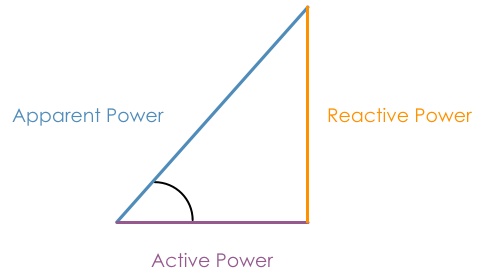
Power triangle relates the apparent power with true or active power & reactive power. It will let you know the ratio of actual power consumed to total amount power taken by the circuit.
And this ratio between actual amount of power consume or active power & total amount of power taken or apparent power is called as Power Factor
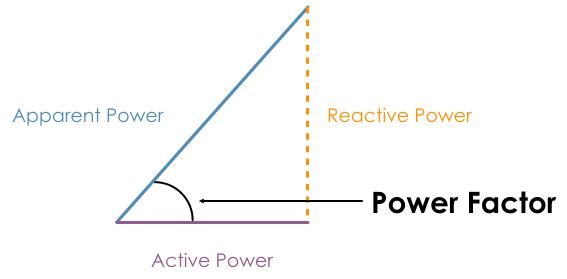
Power factor will tell you the total amount of active power taken by your circuit. Let’s calculate power factor for circuit shown above.
Power Factor = 
Power Factor = 
Remember, power factor is a unit less quantity. So, this means that if the circuit is consuming 100% power, out of which only approx. 70% is active power. So, of course to full fill the 100% requirement of active power, the circuit will consume additional 30% power. And now, the total amount of power consumed by the circuit will be equal to 130%.
If this circuit would have a unity power factor i.e. purely resistive load then we would have been able to deliver 671.85 watts of active power with the same current of 2.93 amps. But as the power factor is low, i.e. 0.76, the active power delivered is 515.094 watts only, and the current is still same 2.93 Amps. This shows how important the power factor is!
Summary
Now, let’s summarise this tutorial.
- Power factor is the ratio between active power & apparent power.
- Power factor indicates the amount of active power circuit is consuming.
- In case of purely resistive circuit, the power factor would be unity or highest, as the reactive power is zero & apparent power is equal to active power.
- In case of purely inductive or capacitive circuit, the power factor would be Zero, as the active power is zero & apparent power is equal to reactive power.