1 Phase Power vs 3 Phase Power
1 Phase Power vs 3 Phase Power https://www.theelectricalguy.in/wp-content/uploads/2020/06/Thumbnail1-1-1024x576.jpg 1024 576 Gaurav Joshi https://secure.gravatar.com/avatar/f6a3006f3f7233a71d79d0e705c167ae12516870e5239627478665ae377435b3?s=96&d=mm&r=gElectrical energy is generated, transmitted and distributed in the form of three phase power. Homes and small premises are connected with single phase power. But most of the time you will find that, 3 phase power is preferred over 1 phase power. 3 phase machineries are more efficient than 1 phase. But why it is like that? Why 3 phase power is preferred over 1 phase and what is the basic difference between 3 phase and 1 phase power? If you want to get the answers and other details about 1 phase and 3 phase power in the easiest way, I would recommend you to watch the video.
Content
1 Phase Power
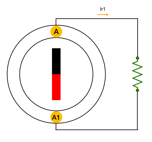
To understand the concept of 3 phase power, we first must understand the 1 phase power. So, consider that we have a generator with one winding and two terminals “A” and “A1”. A permanent magnet which is rotating inside the generator. Some external force let’s say turbine, is driving the magnet.
When this magnet will start rotating, a sinusoidal voltage will get induce across the terminals of the winding. If you connect a resistor across the terminal of the winding, the resistor will start taking current. And if we draw the waveform for current, it will look like this.
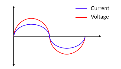
If you observe the waveforms, you’ll find that, current is in phase with voltage. In phase is simply means both voltage and current,
- Start at same time
- Reaches their peak at same time
- And gets zero at same time.
Now, to get the instantaneous power I’ll simply multiply the voltage with current. And the resultant power waveform will look like this.
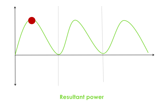
The point highlighted in the above waveform, is peak power point i.e. power at this point is highest. The funny thing about 1 phase power is that, the average power is one half of its peak value. You can do the math and find that if peak power is 2P then the average power is P only. Also, the power output is not constant.
2 Phase Power
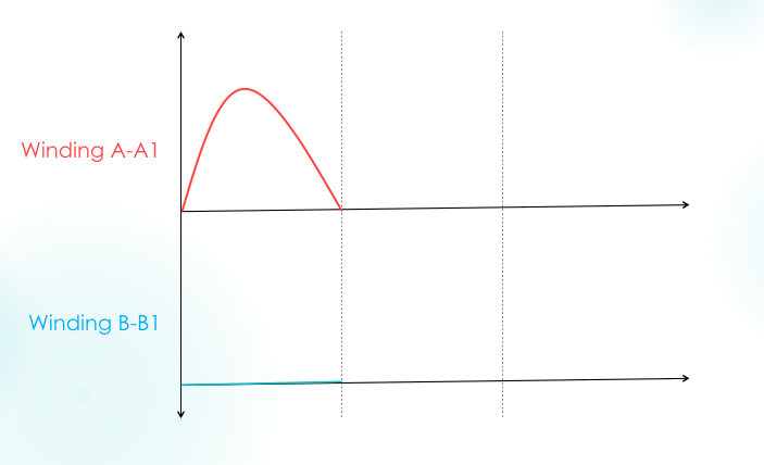
Now, let’s say in the previous single phase generator, I added one more winding with terminal “B” and “B1”, as shown. Please note, the winding B – B1 is displaced 90 deg from winding A – A1.
The interesting part of this arrangement is that, when the magnet is in the initial position shown above, we can observe two things.
- First is, voltage across winding A – A1 is maximum or we can say it is at its peak.
- And second is, voltage across winding B – B1 is almost zero.
This is because, when the magnet is in the initial position, the flux only cuts across the terminal in slot A & A1. So, of course when the magnet will rotate 90 deg mechanically,
- The voltage across winding B – B1 will reach its positive peak
- And the voltage across winding A – A1 will become zero, as shown below.
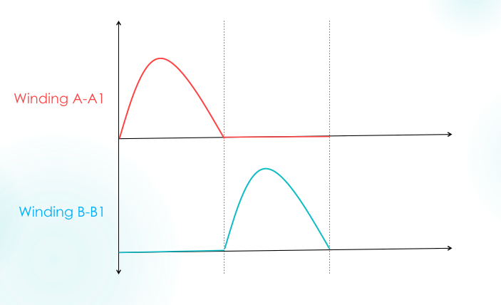
Therefore, we can say that, these two voltages are out of phase by 90 deg. This simply means that, one voltage will reach its peak value before 90 deg than the other.
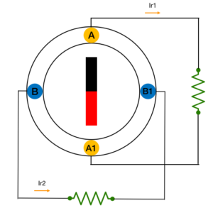
Now, let me connect identical resistors across both the winding. Current Ir1 and Ir2 will start flowing through resistors.
These currents are in phase with their respective voltage, and hence they are also out of phase with each other by 90 deg. The instantaneous power of both the registers will be as shown.
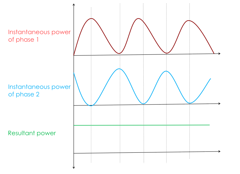
Here you can notice that, when the power output of resistor R1 is zero, power output of resistor of R2 is maximum and vice versa. If we add instantaneous power of both the phases, we’ll find that, the resultant power is constant and equal to the peak power “Pm” of one phase, as shown in above figure.
In conclusion, the power output of 2 phase generator is constant and better than the 1 phase generator.
3 Phase power
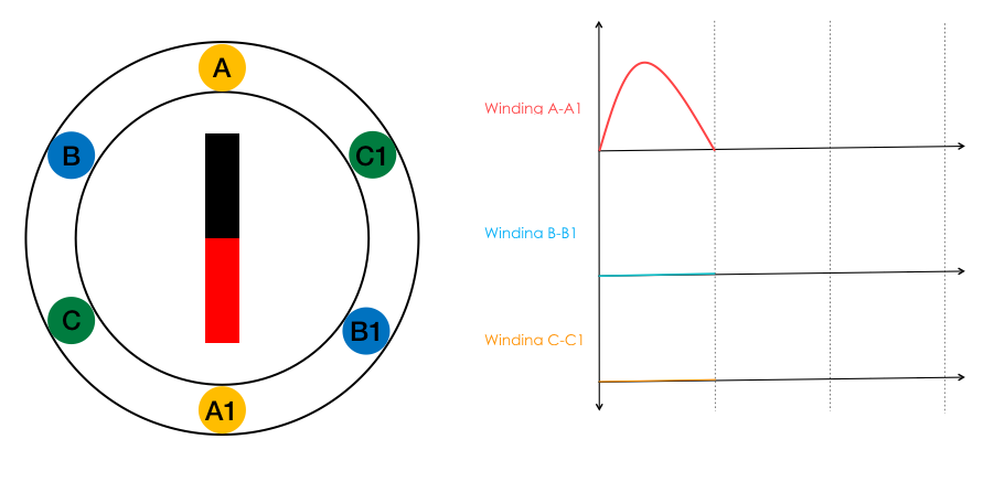
Now, you might have already got why we use 3 phase power but, still to make things more clear, we’ll have a look at 3 phase power. Again, consider our 2-phase generator but this time we’ll add one more winding C – C1 and we’ll place these 3 windings 120 deg apart from each other as shown.
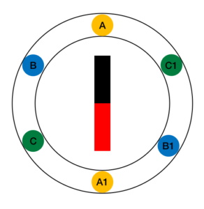
When the magnet we’ll start rotating, an identical voltage will get induce across all the 3 windings. As we have placed windings, 120 deg apart from each other, the voltage induce in 3 phases will also be out of phase by 120 deg. Or simply, voltage of each phase will reach their peak value after 120 deg. Let me make things more clear. When the magnet is in position shown voltage across winding A-A1 is maximum.
When the magnet rotates by 120 deg, voltage across winding B-B1 is maximum.
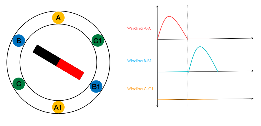
Similarly, when magnet rotates by 240 deg from its initial position, voltage across winding C-C1 gets maximum.

Now, if we connect identical resistors across all the 3 windings. Current Ir1, Ir2 and Ir3 will start flowing through resistors. These currents are in phase with their respective voltage and hence, they are also out of phase with each other by 120 deg.
Again, doing the same procedure we did for 2-phase generator, we’ll find that, the power output we are getting by adding instantaneous power of all 3 phases, is constant and it is (1.5 x Pm) of one phase. So, here we have achieved constant and more power by simply adding two extra windings to a single phase generator.
And this is the reason why 3 phase power is preferred over 1 phase power.
Summary
So, to summarise this topic:
- The 1 phase power output is not constant and the average power is half than its maximum power.
- 2 phase power output is constant at every instant and the average power is equal to the maximum power of one phase.
- 3 phase power is also constant at every instance and the average power is 1.5 times the maximum power of one phase.