5 Types of Power Factor Correction | Capacitor bank locations
5 Types of Power Factor Correction | Capacitor bank locations https://www.theelectricalguy.in/wp-content/uploads/2020/06/05-1024x576.jpeg 1024 576 Gaurav Joshi https://secure.gravatar.com/avatar/f6a3006f3f7233a71d79d0e705c167ae12516870e5239627478665ae377435b3?s=96&d=mm&r=gCapacitor banks is the most commonly used method to improve power factor. In this tutorial, I’ll explain, different type of power factor correction defined by the location of capacitor banks. So, let’s start.
Recommend readings before moving on in this tutorial
- What is Power factor
- Top 4 reasons to improve power factor
- How to improve power factor? The basic principle
- Top 3 ways to improve power factor
In theory, capacitor can be installed anywhere. But we must evaluate the relevant practical and economic feasibility. According to the location of capacitor, following are the types of power factor correction.
- Distributed power factor correction
- Group power factor correction
- Centralized power factor correction
- Combined power factor correction
- Automatic power factor correction
1. Distributed power factor correction
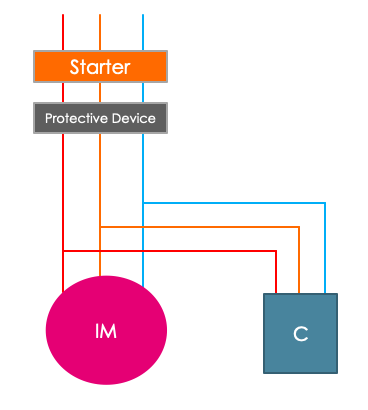
In this type of power factor correction, capacitor banks are directly connected to the terminal of the load which demands reactive power. This type of installation is very economical & simple. Capacitor bank & the load can use the same protective device against over current as shown in below figure. Therefore, it can be connected & disconnected simultaneously.
This type of power factor correction advisable for the large loads which remains connected to the system for long time. Distributed power factor correction is generally used for induction motors & fluorescent lamps.
In case of direct connection as shown in fig 1 & 2, there is a risk that motor keeps running even after the disconnection from the supply.
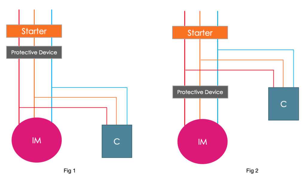
This is because of the residual kinetic energy. And it will self-excite with the reactive energy drawn from the capacitor bank, and may turn into asynchronous generator. Therefore, to avoid this, it is strongly recommended to use separate switching device for capacitor bank as shown in fig 3.
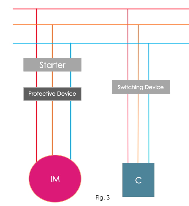
When using the connection shown in fig 3, capacitor bank is switched on after the motor is switched on. And it is turned off before the motor is turned off, which avoids the running of motor after it is turned off.
2. Group power factor correction
This method is generally used for the loads which have similar functioning. A common capacitor bank is provided to improve the power factor, as shown in figure.
So, for instance, if you have 3 similar induction motors which is being used for a same reason, you can use a common capacitor bank for power factor correction. This method is also economical but recommend only for small loads.
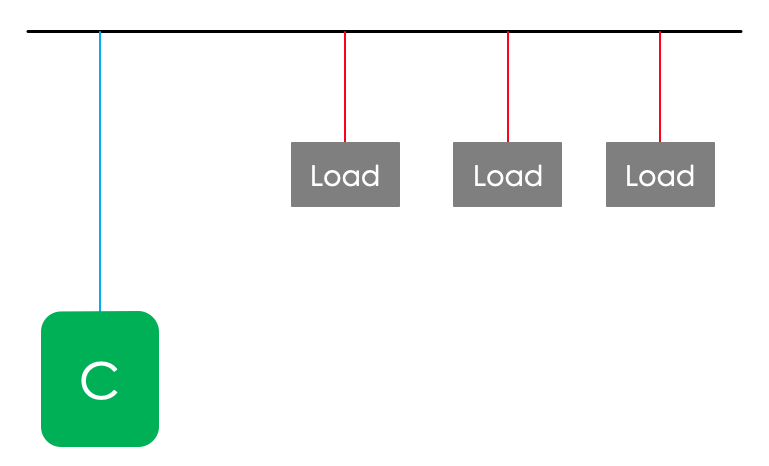
3. Centralize power factor correction

In a system, not all loads are connected for all day. There are some loads, which are turned ON for a very short time. In such cases, use of distributed power factor correction is not a good choice. Therefore, centralized power factor correction is preferred. In which capacitor banks are located at the origin or at the centre of the system. This allows a remarkable reduction in total power of the installed capacitors. The capacitor banks must be installed with a switching device, as keeping capacitor banks connected permanently to the system is not good choice.
4. Combined power factor correction
As the name suggest, it is the combination of two different methods i.e. distributed power factor correction & centralized power factor correction. In this method, distributed power factor correction is used for the large load which runs continuously. And to improve power factor of small equipment, centralized power factor correction method is used.
5. Automatic power factor correction
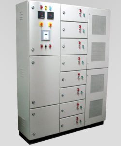
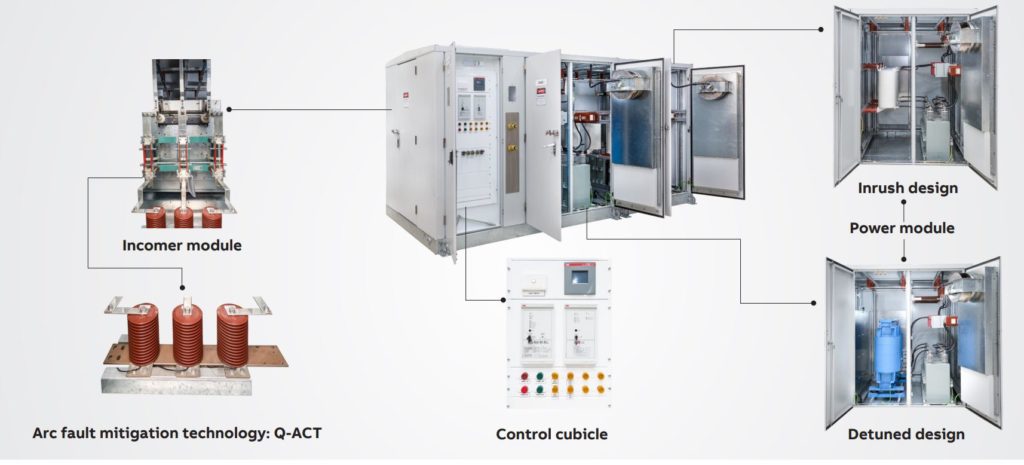
In most of the system, constant absorption of reactive power does not happen, because of the working cycle of the equipment. In such installations, there are systems provided for automatic power factor correction. Which allows the switching of different capacitor banks when needed. This type of automatic power factor control panels or APFC panels are widely used. These types of panels mainly consists of following.
- Sensors for detecting current and voltage
- Switching & protection devices
- An intelligent system which compares the required power factor and current power factor.
Apart from this, capacitor banks must be provided with switching & protective devices. Also, discharge facility shall be provided for capacitors. Now a days most of the capacitor comes with in build discharge resistor.