Top 3 Ways to Improve Power Factor
Top 3 Ways to Improve Power Factor https://www.theelectricalguy.in/wp-content/uploads/2020/06/04-1024x576.jpeg 1024 576 Gaurav Joshi https://secure.gravatar.com/avatar/f6a3006f3f7233a71d79d0e705c167ae12516870e5239627478665ae377435b3?s=96&d=mm&r=gImprove power factor using these 3 ways. Know about the 3 most commonly used ways of improving power factor i.e. capacitor banks, synchronous condenser & Phase advancer. So, let’s start.
In this video, we’ll have a look at the 3 most commonly used ways to improve power factor. So, to get the details, you need to watch the video.
Recommend readings before moving on in this tutorial
- What is Power factor
- Top 4 reasons to improve power factor
- How to improve power factor? The basic principle
So, after understanding how you can improve power factor, it is very clear that, to improve power factor, we need to add equal & opposite amount of reactive power to the circuit. The ways to improve power factor are nothing but the ways to generate equal and opposite reactive power. Three most commonly used ways are –
- Capacitors or capacitor banks
- Synchronous condenser
- Phase Advancers
Reactive power generated by these ways is capacitive in nature, as most of the time the load is inductive load like transformer & induction motor, etc.
Capacitors or capacitor banks
For power factor correction, capacitor or capacitor banks is the most commonly used method. You’ll find them almost everywhere. As we all know most of the time load is inductive, which take lagging current and decreases the power factor. Therefore, to improve power factor, capacitors are installed in parallel with such loads.
Capacitor provides leading current which neutralise the lagging component of inductive load. Thus, the power factor of system improves. We have seen the detail of how this happens in our previous tutorial.
Advantages of Capacitor Banks
- This method of improving power factor is the cheapest one
- Capacitor requires very low maintenance
- Also, it has very low losses.
- Wide range of capacitors available
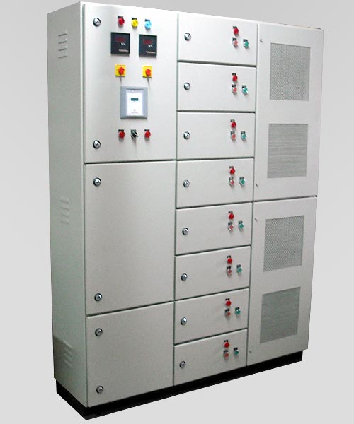
Switching of capacitor banks of high capacity, causes switching surges on the system. APFC panels i.e. Automatic Power Factor Control panel are also used, which automatically makes the switching of capacitors based on the requirements using contactors. APFC panels can supply reactive power ranging from 20kVAR to 1000kVAR (varies with manufactures).
In the next tutorial, we’ll see the different locations for Capacitor banks.
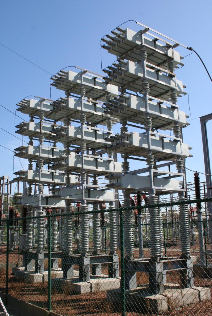
Synchronous condenser
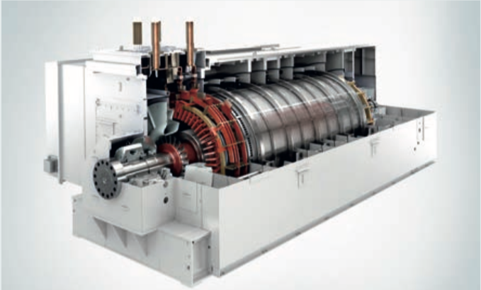
When a Synchronous motor operates at No-Load and over-exited then it’s called a synchronous Condenser. Whenever a Synchronous motor is over-exited then it provides leading current and works like a capacitor. Let’s see how a synchronous motor supplies reactive power?
The mmf needed to produce the constant flux Ø may be produced by either the stator which is connected to 3 phase line or by the rotor which is excited by a DC source or by both. Now, if the rotor excitation current is zero, all the flux has to be produced by stator only, and hence stator must absorb the reactive power from 3-phase line. But if we excite the rotor with a DC current, rotor’s mmf will help to produce the part of required flux, and less reactive power will be drawn from the 3 phase line. If we raise the excitation of rotor, it will produce all the required flux by itself, and no reactive power will be drawn form 3 phase line. Now, we can say the power factor of motor is unity.
If we over excite the rotor what will happen? Stator, instead of absorbing reactive power will actually start delivering it. The motor then behaves like a source of reactive power, just as it were a capacitor. Of course, the level of excitation depends on how much reactive power you want. Synchronous Condenser can also be linked with PLC based controller with PF controller and regulator, which will automatically control the excitation and generate the required reactive power.
Synchronous Condenser are generally used by large power users as it is very costly.
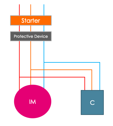
Phase Advancer
Phase advancer are mainly used to improve power factor of induction motors. It is a simple AC exciter which is connected on the main shaft of the motor and operates with the motor’s rotor circuit for power factor improvement.
Frankly speaking, I don’t have much information about phase advancer. But, the principle is same. As induction motor is inductive in nature, it takes lagging current from the system & phase advancer provides leading current. Which eliminates the reactive component which will further improve power factor of the motor.
Summary
So, let’s summarise this tutorial.
- Power factor improvements methods are nothing but means of generating reactive power.
- Most commonly used methods are capacitor banks, synchronous condenser & Phase advancer.
- Capacitor banks are most commonly used as they are very cheap and requires less maintenance.
- Synchronous condenser is generally preferred by large power customers, as the cost is very high.
- Phase advancer is used for PF improvement of induction motor.
In the next tutorial, we’ll learn about the 5 different types of power factor correction based upon locations of capacitor banks.