Nameplate details of SF6 Circuit Breaker | Explained
Nameplate details of SF6 Circuit Breaker | Explained https://www.theelectricalguy.in/wp-content/uploads/2020/06/Nameplate-CB-1024x576.jpg 1024 576 Gaurav Joshi https://secure.gravatar.com/avatar/f6a3006f3f7233a71d79d0e705c167ae12516870e5239627478665ae377435b3?s=96&d=mm&r=gIn this post, we will delve into the nameplate parameters of a SF6 circuit breaker. These parameters are universally applicable to high and extra-high voltage class SF6 circuit breakers. Also, many of these parameters will be applicable for medium voltage breakers as well. So, without further ado, let’s get started.
In most of the countries high & extra high voltage circuit breakers are manufactured based on the IEC standard, i.e. IEC 62271-100. Parameters mentioned on the nameplate of circuit breaker are in line with the IEC 62271-100.
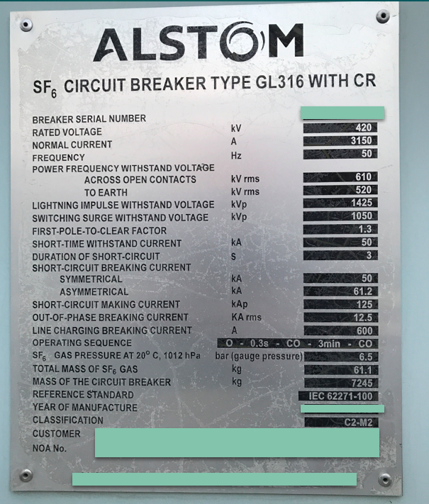
Nameplate of 420kV SF6 Circuit Breaker
As per IEC, few parameters are mandatory, some are condition based, and some of them are completely optional. In this post, you’ll learn about all these parameters mentioned on nameplate of SF6 circuit breaker.
Mandatory Parameters
- Manufacturer
- Type designation and serial number
- Year of manufacture
- Relevant standard
- Rated Voltage
- Rated Frequency
- Rated normal current
- Rated short circuit breaking current
- Rated duration of short circuit
- Rated peak withstand current or rated making current
- Rated short duration power frequency withstand voltage (kV) & Rated lighting impulse withstand voltage (kVp)
- Rated operating sequence
- Rated pressure of SF6 gas
- Total weight of SF6 gas
- Total weight of CB
- Rated control voltage
Condition based parameters
- Rated switching impulse withstand voltage
- DC component of short circuit current
- Rated line charging current
- Classification
Optional Parameters
- Rated out of phase current
- Rated cable changing
- Rated single capacitor bank breaking current
- Rated back to back capacitor bank breaking current
Mandatory Parameters
As the name suggest, these parameters are mandatory. All the manufacturer producing circuit breakers must mention these parameters on the nameplate of SF6 circuit breaker. But of course, some of these parameters may be skipped, if it is mutually agreed between manufacturer and customer.
Rated voltage
Rated voltage is the “Highest system voltage” for which breaker is designed. This voltage is mentioned in kV rms and refers to phase to phase voltage of 3 phase system.
Most of the time people gets confused between rated voltage and normal voltage. Rated voltage is the highest voltage of a system for which the system is designed. Whereas, normal voltage is the voltage which will remain in the system normally. And as per the system design guidelines, rated voltage must be higher than the normal system voltage. So, in this case, 420kV is the rated voltage and 400kV is normal voltage. Similarly, for 245kV voltage level, rated voltage is 245kV and the normal voltage is 220kV. For 145kV, rated voltage is 145kv and normal voltage is 132kV.
Unit : kV RMS
Rated frequency
It is the power frequency on which electricity is generated, transmitted and distributed. In some countries it is 50Hz and in some it is 60Hz.
Unit : Hz
Rated normal current
It is the rms value of rated current which circuit breaker can carry continuously. Or simply, we can say that, this is the normal current of the system.
Unit : Ampere
Following are some of the standard values of rated normal current-
- 400 A
- 630 A
- 800 A
- 1250 A
- 1600 A
- 2000 A
- 3150 A
- 4000 A
Short circuit breaking current
It is the highest rms value of short circuit current, which circuit breaker is capable of breaking. Rated short circuit current sometimes also called as symmetrical breaking current.
On some nameplates, you’ll find that short circuit current is given as symmetrical and asymmetrical current. The difference is that, Symmetrical current is the AC component of short circuit current which is equal to rated short circuit current. Whereas, asymmetrical current is the combination of AC and DC components of short circuit current.
So, you can see in the above nameplate, asymmetrical current is greater than the symmetrical.
Unit : kA RMS
Rated duration of short circuit
It is the time in seconds for which the breaker can withstand the short circuit current. As per standards it can be 3 sec or 1 sec.
Unit : Seconds
Students’ Feedback for our course on Circuit breaker control Schematics !!


Rated peak withstand current or Rated making current
If the circuit breaker closes during the existing fault, current may increase to a very high value during the first cycle. Therefore, the breaker must withstand this high current and the mechanical forces caused by this current. This current is called as “short circuit making current”. Or it is also called as rated peak withstand current.
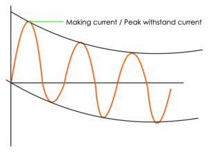
It is generally 2.5 times the rated short circuit current. It is referred in kA peak, as it remain for very short time.
Unit : kA Peak
Rated short duration power frequency withstand voltage
This is one of the highest system voltages use to check the insulation properties of the equipment. It can also be called as insulation levels, if we combine rated lighting impulse voltage and switching impulse voltage (which is a condition based parameter).
Power frequency withstand voltage can be caused by these reasons
- Phase to earth faults
- Load rejection
- Ferro resonance
- Ferranti effect
And hence, breaker shall withstand power frequency voltage caused by these reasons. IEC has defined the level of power frequency voltage that can appear across breaker contact. So, for example, for 420kV CB the power frequency voltage defined by IEC is 610kV rms. Circuit breaker has to undergo power frequency withstand test, in which power frequency voltage is applied to the circuit breaker for 1 min.
Unit : kV RMS
Rated lighting impulse withstand voltage
Lighting impulse voltage is generally generated due to lighting strokes. And of course, breaker has to withstand these voltages too. Based on the experience and system studies, IEC has defined the values for this also. For 420kV voltage level, lighting impulse voltage defined by IEC is 1425 kV peak. Breaker has to undergo test for this also.
Unit : kV Peak
First pole to clear factor
In SF6 circuit breaker, arc extinguishes during current zero. As in 3 phase AC circuit, currents are out of phase by 120°, current interruption in breaker is not simultaneous. Contact of one pole will open before the other two. And hence, the power frequency recovery voltage across the first pole to open is more than the other two. And this is called as first pole to clear factor. It is given as times the normal system voltage.
So, on the nameplate you’ll find it is mentioned as 1.3 (or 1.5). This means, first pole to open will have 1.3 times the normal system voltage across it, and the pole can sustain that.
Unit : N/A
Here is the detailed video on First pole to clear factor.
Rated operating sequence
This is one of the important parameter of the breaker, it is also known as “Auto reclosing duty”.
Operating sequence denotes the opening & closing operation breaker is capable of performing under specified conditions.
As per IEC 62271-1 there are two alternatives for operating sequence,
O – t – CO – t’ – CO
CO – t’’ – CO
where,
O = Opening operation
C = closing operation
t,t’,t’’ = time intervals between successive operations
Let me tell you how auto reclosing works. 90% of the faults (like ) on the system are transient in nature. Which remain in the system for a very short time and then the system goes back to normal. In such cases, it is beneficial to put the system live again, and here the auto reclosing system comes into picture.
We’ll consider the auto reclosing duty which is mentioned on our nameplate i.e. O-0.3 SEC-CO-3 MIN-CO. So, let’s say there is fault on the system the breaker will open then it will remain open for 0.3 sec. After 0.3 sec, it will close and if the fault is cleared it will remain close. But, if the fault is still there then the breaker will open immediately. Now breaker will remain in open condition for 3 mins. After 3 mins the breaker will close again, and if the fault is cleared it will remain close. But if, the fault is still there then the breaker will open immediately, and now breaker will remain open until it is closed manually.

Unit : N/A
Here is the video on operating sequence of circuit breaker.
Rated pressure of SF6 gas
This is the rated pressure of the SF6 gas in the breaker. This will vary manufacturer to manufacturer.
Unit : Bar or mega pascals or kg/ sq. cm.
Total weight of SF6 gas
This shows the total weight of SF6 gas in the breaker. Again, this will vary manufacturer to manufacturer.
Unit : kg
Total weight of CB
This shows the total weight of SF6 gas in the breaker. Again, this will vary manufacturer to manufacturer.
Unit : kg
Rated control voltage
This is the DC voltage on which closing and tripping coil works. It can be 110V DC or 220V DC.
Unit : Volts
These were the mandatory parameters as per IEC. These parameters you’ll generally find on every nameplate of high & extra high voltage SF6 circuit breaker.
Condition Based parameters
Now, let’s see condition based parameters. These parameters depends upon some specific condition, which is also given below. If that condition is satisfied, then these parameters has to be on nameplate of the circuit breaker.
Rated switching impulse withstand voltage
Condition : Applicable only for circuit breakers including & above 300kV
Switching surges are generally occurs above 245kV voltage level. And hence you’ll only find this parameter on the circuit breaker above 245kV level.
It becomes important to test the breaker above 245kV voltage level for switching surges. Switching surges are generally caused by energisation of lines or switching of transformers, etc. For 420kV voltage level, switching voltage is specified as 1050kV peak.
Unit : kV Peak
DC component of short circuit current
Condition : It has to be on nameplate if it is more than 20%
DC component is a DC component of short circuit current. And if it is more than 20% at the time of contact separation of CB, then it has to be on name plate.
Unit : %
Rated line charging current
Condition : Applicable only for circuit breakers including & above 72.5kV
This is the highest amount of line charging current a circuit breaker is capable of breaking. This type of current is generated because of the switching of loaded or unloaded overhead lines. So, for 420kV CB IEC has defined the rating equal to 600A.
Unit : Ampere
Classification
Condition : If class in not E1 & M1
If circuit breakers mechanical endurance class and electrical endurance class is different from M1 and E1, then it has to be on nameplate. Let me tell you what is mechanical endurance class and electrical endurance class.
Mechanical Endurance Class
- M1 Class
If the breaker is of M1 class which is also called as normal mechanical endurance class, then the breaker has to withstand 2000 no load operations. - M2 Class
If the breaker is of M2 class which is also called as Extended mechanical endurance class, then the breaker has to withstand 10,000 no load operation.
Electrical Endurance Class
E1 stands for Electrical endurance. Generally most of the breaker nowadays are of E1 class. E2 class is an extended electrical endurance class which indicate that, the interrupting parts of the breaker does not require maintenance during its expected operating life.
Please note, as per IEC 62271-100 E2 class is limited to distribution circuit breaker upto 52kV.
C1 & C2 class of circuit breaker
On the nameplate, if you see, it is mentioned as M2 & C2. M2 class we just saw. But what is C2 class? Let’s see that. Breaker with class C1 indicates, “Low probability of restrike during breaking of capacitive currents”. Whereas, C2 class breaker indicates, “very low probability of restrike during breaking of capacitive currents”.
So, this was about the condition based parameters. Now let’s look at the optional parameters.
Optional Parameters
These parameters are completely optional as per the IEC standard. And hence, it can be or cannot be on the nameplate, depends upon the manufacturer.
Rated out of phase current
If the breaker is used for synchronising two different system, it may happen that the breaker has to open when the systems are in synchronism procedure. And the current generated during this condition is called as out of phase current.
This current gives the highest amount of transient recovery voltage across the breaker contacts and hence it is one of the critical duty to break. Generally, out of phase breaking current is 25% of rated short circuit breaking current. On the nameplate you can see the out of phase current is 12.5kA which is 25% of rated short circuit breaking current I.e. 50kA.
Unit : kV
Rated cable Charging
This is the highest amount of cable charging current a breaker is able to break. Cable charging current can occur while switching the unloaded cables.
Don’t get confused between line charging and cable charging both are different. Line charging refers to overhead lines whereas, cable charging refers to underground cables.
Unit : Ampere
Rated single capacitor bank breaking current
This is the highest amount of a single capacitor bank current a breaker is capable of breaking. Switching of capacitive and inductive current is a bit difficult task for the breaker. Because, voltage and current in capacitive and inductive circuit is not in phase with each other.
Unit : Ampere
Rated back to back capacitor bank breaking current
Back to back capacitor bank switching is a special application, and not all the breakers are intended for this. While switching back to back capacitor banks, inrush current is very high and hence there is a high possibility that the arc will restirke. So, if the breaker is made for back to back capacitor bank switching, then you’ll find this parameter on the nameplate of SF6 circuit breaker.
Unit : Ampere
So, these are the optional parameters you can find on the name plate of HV or EHV circuit breaker.
So, that is all for this post. I hope you have learned about all the different parameters about the circuit breaker. If you found this post helpful then do share this post with the people you think might be interested to learn about all these parameters. Also, highly recommend to have a look at our course on circuit breaker control schematics in which you’ll learn all about the secondary wiring & logic of the circuit breaker.
Circuit breaker control schematic Masterclass | Beginner to Advanced