Nameplate details of Capacitive Voltage Transformer (CVT) | Explained
Nameplate details of Capacitive Voltage Transformer (CVT) | Explained https://www.theelectricalguy.in/wp-content/uploads/2020/06/CVT-1024x576.jpg 1024 576 Gaurav Joshi https://secure.gravatar.com/avatar/f6a3006f3f7233a71d79d0e705c167ae12516870e5239627478665ae377435b3?s=96&d=mm&r=gCapacitive voltage transformer is mainly used for measurement of voltage and for protection purpose. It is also used for power line communication between different substations. In this tutorial, we are going to have details of the parameter which are mentioned on a nameplate of CVT or capacitive voltage transformer. So, to get these details read the following tutorial.
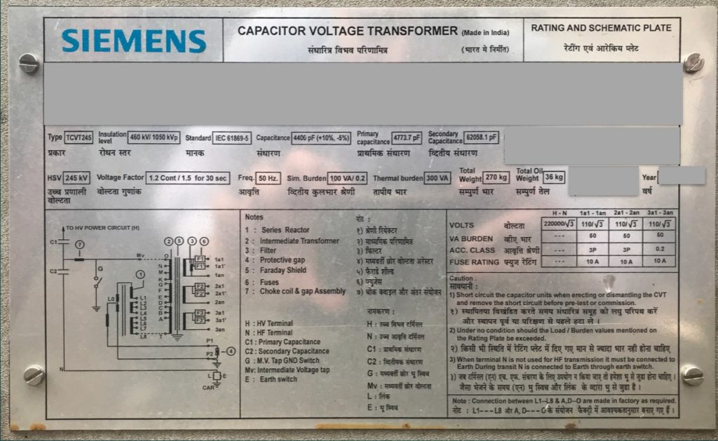
Nameplate of CVT
In most of the countries capacitive voltage transformers are manufactured as per IEC 61869 – 5. This IEC also gives us the parameters which should be marked on the nameplate of CVT or capacitive voltage transformer. The parameters are given below. we’ll see these parameters one by one.
- Name of the manufacturer
- Insulation level
- Standard
- Capacitance
- Primary capacitance
- Secondary capacitance
- Highest system voltage
- Rated Voltage factor
- Rated frequency
- Simultaneous burden
- Thermal burden
- Total weight of CVT
- Total weight of oil
- Year of manufacturing
- Primary and secondary voltage
- VA burden
- Accuracy class
- Fuse rating
1. Name of the manufacturer.
This will show you the name of the manufacturer.
2. Insulation level.
Now, here you can see there are two values mentioned one is in RMS and other is in Peak. So, let’s understand what are these values. The first value, which is mentioned in kV rms, is called as Power frequency withstand voltage, and the second one mentioned in kV peak is called as Lighting impulse voltage. These are the highest system voltages use to check the insulation properties of the equipment. It can also be called as insulation levels, if combined, which you can seen on the nameplate.
Power frequency withstand voltage can be caused by these reasons.
- Phase to earth faults
- Load rejection
- Ferro resonance
- Ferranti effect
Lighting impulse voltage is generally caused due to lighting strokes. Voltage generated due to these reasons can cause insulation failure of CVT or any other equipment, and hence it is important to check the insulation properties the equipment. And to do so, power frequency withstand and lighting impulse test is performed as per the relevant standard. So, on the above nameplate of CVT, you can see, for 245kV voltage level, the values defined are 460kV rms for power frequency and 1050 kV peak for lighting impulse.
3. Standard.
This will give information about the standard as per the equipment is manufactured. In the above nameplate of CVT, it is mentioned as IEC 62271-5.
4. Capacitance.
CVT is the combination of two series capacitance C1 & C2, as shown on the nameplate.
And the equivalent capacitance of C1 & C2 is given on the nameplate of CVT which is 4400pf, in our above case. Values mentioned in bracket is the allowed tolerance in the equivalent capacitance. Standard values of equivalent capacitance are 4400pf, 6600pf & 8800pf.
5 & 6. Primary & Secondary capacitance.
As we know, CVT is the combination of two capacitance C1 & C2. C1 is called as primary capacitance, whose value we can find on the nameplate. Similarly, C2 is called as secondary capacitance whose value is also mentioned on the nameplate of CVT. So, if you calculate equivalent capacitance of these two capacitors, you’ll get the value equal to 4432.8pf which is within the tolerance. But remember one thing, values of C1 & C2 can be different for different manufacturer based on their design. Value of C1 & C2 really doesn’t matter, until we are getting equivalent capacitance equivalent to 4400pF or any other desired equivalent capacitance.
7. Highest system voltage.
This is the highest system voltage for which the CVT is designed. This is also called as rated voltage. So, on the nameplate it is mentioned as 245kV.
Most of the time people gets confused between rated voltage and normal voltage. Rated voltage is the highest voltage of a system for which the system is designed. Whereas, normal voltage is the voltage which will remain in the system normally. So, in this case 420kV is the rated voltage and 400kV is it’s normal voltage. Similarly, for 245kV voltage level, rated voltage is 245kV and the normal voltage is 220kV. For 145kV, rated voltage is 145kv and normal voltage is 132kV.
8. Rated Voltage factor.
On the nameplate of CVT, you can see it is mentioned as 1.2 continues & 1.5 for 30 seconds. What does it indicate? Let’s see that.
First thing is the number mentioned here are in per unit system i.e 1.2 PU & 1.5 PU. Voltage factor indicate highest voltage, CVT can carry for specific time. So, it is mentioned as 1.2 continues this indicate that the CVT can carry 120% of rated voltage continuously. 120% of 245kV is 294kV and the CVT can carry 294kV voltage continuously.
Similarly, it is also mentioned that, CVT can carry 150% (1.5) of rated voltage i.e. 367.5kV for 30 seconds. This feature is required when the system is undergoing over voltages or voltage swells.
9. Rated frequency.
This is power frequency on which the power is generated transmitted and distributed. In some countries it is 50 Hz and in some it is 60.
10. Simultaneous burden.
This indicates how much apparent power we can take at the same time, from all the provided windings, without affecting the accuracy of a particular core. This particular core is given by the customer. In the above nameplate, customer has defined the core as 0.2 class (metering core).
Secondary windings of CVT are generally connected on a same core. Therefore, the burden connected on the one winding may affect the accuracy of other winding. And hence, it is specified that, how much amount of total VA burden you can connect on all the windings of CVT, without affecting the accuracy of 0.2 class (or any other class). On our nameplate, it is mentioned as 100VA, which means we can connect total 100VA on all the windings put together, and still get the accuracy of 0.2.
What will happen if the total burden goes above 100VA?
— Well, accuracy of 0.2 class will not be guaranteed.
11. Thermal burden.
This indicates the total amount of apparent power we can take form CVT at a same time, without increasing the temperature of CVT above the specified limits by IEC or any relevant standard. On the above nameplate of CVT, it is mentioned as 300VA. Which indicates, we can take up to 300VA power from the CVT without increasing the temperature of CVT.
12. Total weight.
This will give us the total weight of CVT in kilograms.
13. Total weight of oil
This will give us the total amount of oil used in CVT in kilograms. Oil is used in CVT for insulation & cooling purpose.
14. Year of manufacturing.
This will show the year in which the CVT is manufactured.
Now on the nameplate, you can see there is table given on the right hand side. Let’s see the details of parameters given in this table.
15. Primary and secondary voltage.
Primary voltage you can see mentioned as 220000V / root 3. Remember one thing, instrument transformers are single phase devices. CVT is connected across phase and neutral. And that’s why, the voltage is divided by root 3.
Similarly, the secondary voltage is given as 110V / root 3. This CVT has 3 different windings and hence you can see secondary voltage is mentioned 3 times. So, secondary voltage of each winding is 110V/root 3.
As per IEC, 100V / root 3 or 110V / root 3 are the standard values of secondary voltages.
16. VA burden.
Now, whatever circuit you are going to connect to the secondary winding of CVT, it is called as burden. This includes the equipment which we are going to connect to the secondary like relay or meter. Also, the wires we are going to use to connect these equipment to the secondary winding.
So, as per the nameplate shown above, we can connect burden up to 50VA on each windings. Standard values of secondary burdens as per IEC are, 1VA, 2.5VA, 5VA, 10VA, 25VA, 50VA, 100VA.
17. Accuracy class.
As we know, CVT can be used for measuring as well as protection purpose. And hence, different windings are used for different purposes. There will be a separate winding provided for metering purpose and separate for protection purpose. Providing separate windings offers many advantages.
Metering classes of CVT as per IEC
- 0.2
- 0.5
- 1
- 3
These numbers have specific meaning to it. For instance, accuracy class of 0.2 indicates, voltage error equal to plus or minus 0.2% is allowed. Similarly, 0.5 class indicates voltage error equal to plus or minus 0.5% is allowed. Class 1 indicate error of 1% and class 3 indicate error of 3%. so, the lesser is the voltage error the more accurate CVT is. Generally, 0.2 class is preferred for tariff metering.
Protection classes of CVT as per IEC
- 3P
- 6P
3P class means, even if we apply 2% of rated voltage to CVT, the voltage or ratio error should be within plus or minus 6%. Similarly, 6P class means, even if we apply 2% of rated voltage to CVT, the voltage or ratio error should be within plus or minus 12%. So, of course 3P class is more accurate and better than the 6P class.
So, as you can see on the nameplate out of three, two windings are used for protection purpose with accuracy class of 3P, and remaining winding is used for metering purpose with the accuracy class of 0.2.
18. Fuse rating.
On the secondary windings, fuses are provided for protection purpose which you can see here.
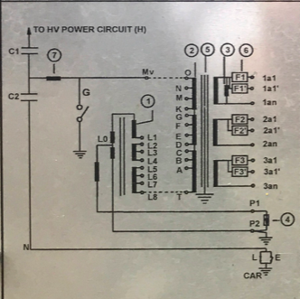
F1, F2 & F3 indicate the different fuses used for three different windings. And the rating of the fuse is 10A. Instead of fuses, one can also use MCBs.
So, these are the parameters you’ll generally find on a nameplate of CVT.