Vacuum Circuit Breaker Nameplate Details | Explained
Vacuum Circuit Breaker Nameplate Details | Explained https://www.theelectricalguy.in/wp-content/uploads/2020/07/Thumbnail-1-1024x576.jpg 1024 576 Gaurav J https://secure.gravatar.com/avatar/87a2d2e0182faacb2e003da0504ad293?s=96&d=mm&r=gGenerally, Vacuum circuit breaker is used below 72.5kV voltage level. In this tutorial, you’ll learn about the parameters which are mentioned on a nameplate of vacuum circuit breaker. So, let’s start.
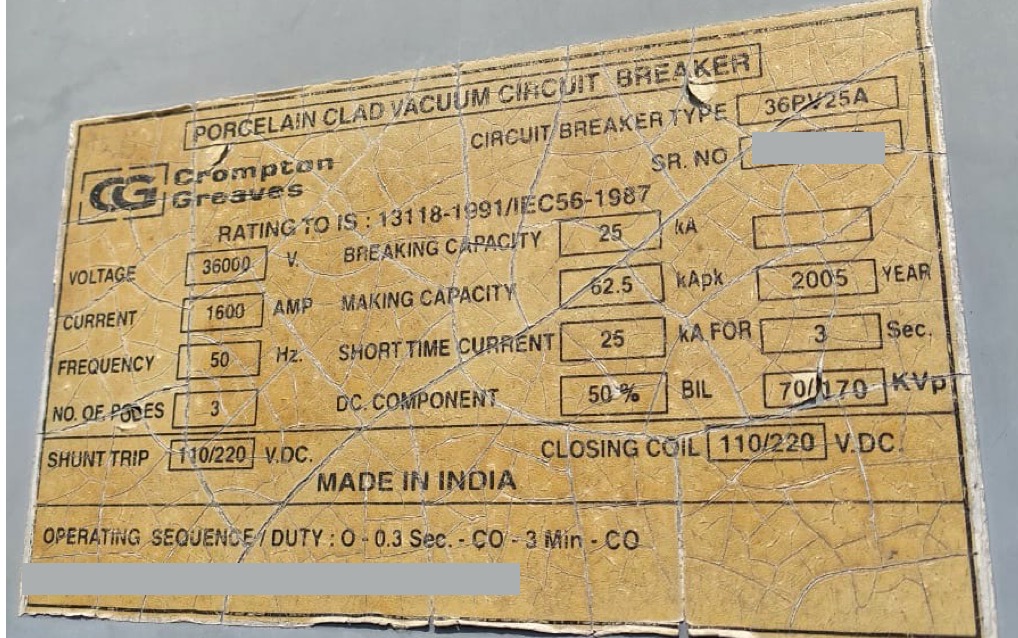
1. Circuit Breaker Type
Few manufacturer also called this as designation. This simply represents, what manufacturer calls the product. In simple language it is the name given by the manufacture to the product.
2. Serial No
It’s a serial number of the breaker. This has to be on the nameplate.
3. Reference IS & IEC standard
This tells us about the standard based on which the circuit breaker is manufactured. For this case it is IS:13118 and IEC 56. This IEC 56 is now withdrawn and it is replaced by IEC 62271-100, which applies to the alternating current circuit breakers.
4. Rated Voltage
Rated voltage is the “Highest system voltage” for which breaker is designed. This voltage is mentioned in kV rms or volt rms and refers to phase to phase voltage of 3 phase system.
Most of the time people gets confused between rated voltage and normal voltage. Rated voltage is the highest voltage of a system for which the system is designed. Whereas, normal voltage is the voltage which will remain in the system normally. So, in this case 36kV is the rated voltage and 33kV is it’s normal voltage. Similarly, for 245kV voltage level, rated voltage is 245kV and the normal voltage is 220kV. For 145kV, rated voltage is 145kv and normal voltage is 132kV.
5. Rated Current
This is the rated current for which circuit breaker is design. Circuit breaker is able to carry 1600A without any problem.
6. Frequency
It is the power frequency on which electricity is generated, transmitted and distributed. In some countries it is 50Hz and in some it is 60Hz.
7. Number of pole
This is equivalent to number for phases. On this nameplate it is mentioned as 3. So, the breaker is 3 phase breaker, R-Y-B. You can ask, all the breakers must be three phase breakers by default. No, that’s not the case. In few cases single pole breaker or single phase breaker is also used. Also, in railway application 2 pole or 2 phase breakers are used.
8. Breaking Capacity
It is the highest rms value of short circuit current, which circuit breaker is capable of breaking. Rated short circuit current sometimes also called as symmetrical breaking current. This breaker is capable of breaking 25kA.
9. Making Capacity
If the circuit breaker closes during the existing fault condition, current may increase to a very high value during the first cycle. Which means, it remains in the system for a very short time. Therefore, the breaker must withstand this high current and the mechanical forces caused by this current. This current is called as “short circuit making current”. Or it is also called as Rated peak withstand current.
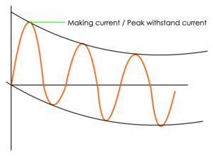
It is generally, 2.5 times the rated short circuit current at 50HZ frequency. It is referred in kA peak, as it remain for very short time. So, if you multiple 2.5 with 25kA, that will give us 62.5kA as the making current.
10. Short time current
This is a short circuit current of the system which may occur in case of fault. And this current may remain in the system for 3 sec. As we have seen, our breaker is also capable of breaking 25kA short circuit current.
11. DC Component
Short circuit breaking current can be expressed in two values. One is the rms value of AC component. And another one is the DC component at the time of contact separation. On the nameplate dc component is mentioned as 50%.
12. BIL or Basic insulation levels
The first value i.e. 70kV represents, Rated short duration power frequency withstand voltage. Power frequency withstand voltage can be caused by these reasons
- Phase to earth faults
- Load rejection
- Ferro resonance
- Ferranti effect
And hence, breaker shall withstand power frequency voltage caused by these reasons. IEC has defined the level of power frequency voltage that can appear across breaker contact. Circuit breaker has to undergo power frequency withstand test, in which power frequency voltage is applied to the circuit breaker for 1 min. So, this 70kV represents that the breaker can withstand power frequency voltage of 70kV
The next value I.e. 170kVp, represent Rated lighting impulse withstand voltage
Lighting impulse voltage is generally generated due to lighting strokes. And of course, breaker has to withstand these voltages too. Based on the experience and system studies, IEC has defined the values for this also. Breaker has to undergo test for this also.
Please note, these value for insulation level is for altitude level less than or equal to 1000 meter above sea level. If the altitude level is more than 1000 meters, an altitude correction factor needs to applied to these value. For instance, the values 70kV & 170kVp are for altitude of 1000 meter. If the altitude level is let’s say 1200 meter, then defiantly these values will change. It will be more than the values specified on the nameplate shown.
13. Control Voltage
Next you’ll see, voltage rating of trip coil and closing coil is mentioned. Trip coil is also called as shunt trip coil. This voltage is generally DC, because the function of closing coil & tripping coil is very much important. And hence, it needs to have a steady & constant supply. Which can be provided by battery banks. This voltage is also called as control voltage, as it is controlling the opening & closing operation of breaker. Generally, it is either 110V DC or 220V DC at least in India. I am not certain, why both 110V & 220V DC is mentioned on this nameplate. It’s a very rare case where dual control voltages are provided.
14. Operating Duty
This is one of the important parameter of the breaker, it is also known as “Auto reclosing duty”. Operating sequence denotes the opening & closing operation breaker is capable of performing under specified conditions.
As per IEC 62271-1 there are two alternatives for operating sequence,
O – t – CO – t’ – CO
CO – t’’ – CO
where,
O = Opening operation
C = closing operation
t,t’,t’’ = time intervals between successive operations
Let me tell you how auto reclosing works. 90% of the faults (like ) on the system are transient in nature. Which remain in the system for a very short time. And then, the system goes back to normal. In such cases, it is beneficial to put the system live again. And here, the auto reclosing system comes into picture.
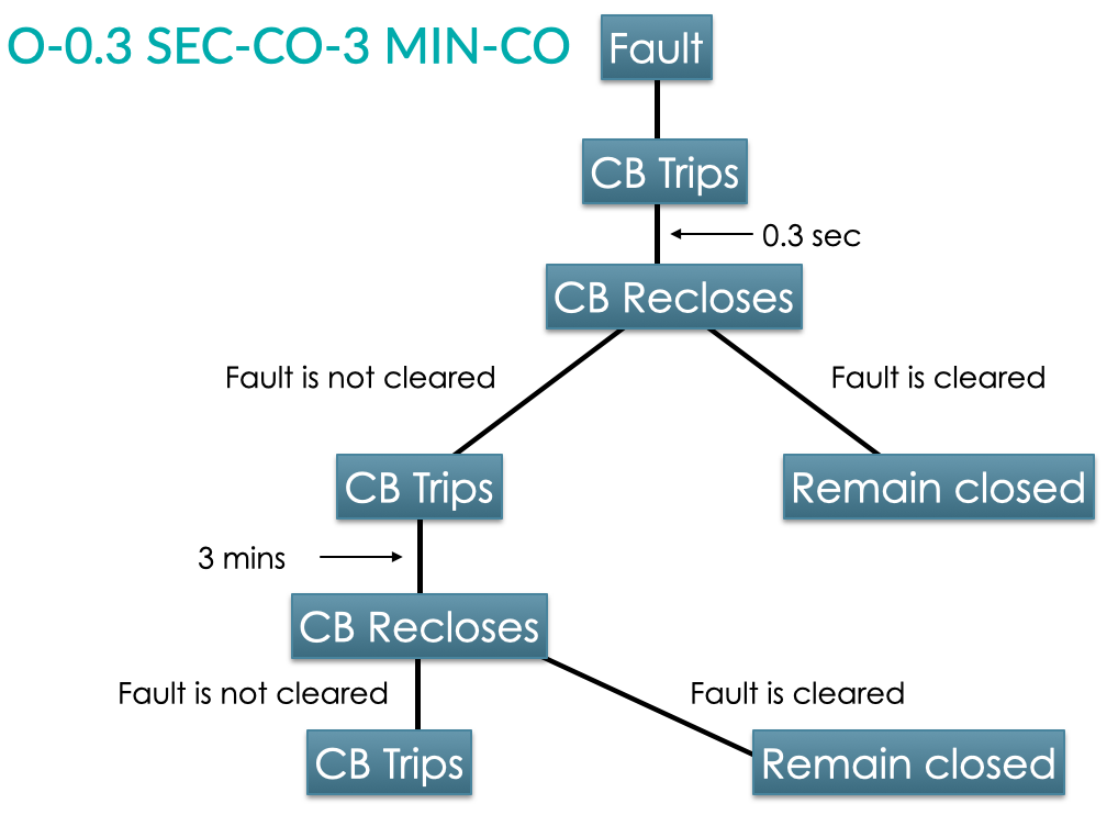
We’ll consider the auto reclosing duty which is mentioned on our nameplate i.e. O-0.3 SEC-CO-3 MIN-CO. So, let’s say there is fault on the system. And hence, the breaker will open. Then it will remain open condition for 0.3 sec. After 0.3 sec, it will close again automatically and if, the fault is cleared it will remain in close condition. But, if the fault is still there then the breaker will open immediately. Now, breaker will remain in open condition for 3 mins. After 3 mins, the breaker will close again, and if the fault is cleared it will remain close. But if, the fault is still there then, the breaker will open immediately. And now breaker will remain open until it is closed manually.
It is one of the very useful feature of circuit breaker.
So, this covers all the parameters mentioned on the nameplate of a VCB. If you want to know the nameplate details of other substation equipment, you can check out my playlist Nameplate details of Substation Equipment.