


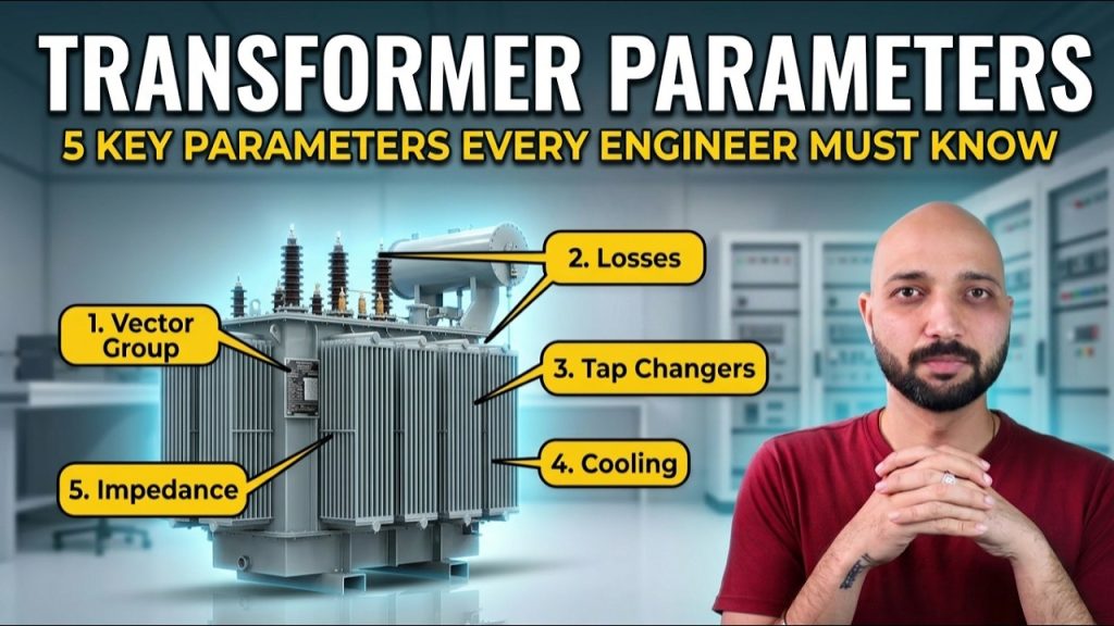
5 Transformer Parameters Explained for Electrical Engineers
5 Transformer Parameters Explained for Electrical Engineers https://www.theelectricalguy.in/wp-content/uploads/2026/05/maxresdefault-6-1024x576.jpg 1024 576 Gaurav Joshi https://secure.gravatar.com/avatar/f6a3006f3f7233a71d79d0e705c167ae12516870e5239627478665ae377435b3?s=96&d=mm&r=gTwo transformers may have the same voltage rating and the same MVA rating. Still, both transformers may behave differently in actual operation. That is why understanding important transformer parameters becomes very important for every electrical engineer.
These parameters help engineers understand transformer behavior, losses, cooling, voltage regulation, and short circuit performance. They also help determine whether two transformers can operate in parallel safely.
Let us understand the five important transformer parameters step by step.
Table of Contents
- Vector Group of Transformer
- Transformer Losses
- Tap Changers in Transformers
- Cooling Methods of Transformer
- Transformer Impedance
- Conclusion
1. Vector Group of Transformer
The vector group is one of the most important transformer parameters. You may have seen codes like Dyn11 or YNd1 written on transformer nameplates. These are not random letters and numbers. Each part has a specific meaning.
The capital letter represents the HV winding connection.
- D means delta connection
- Y means star connection
The small letter represents the LV winding connection.
- d means delta connection
- y means star connection
The letter N or n indicates neutral availability. It shows whether neutral is available on the HV side, LV side, or both sides.
The number represents phase displacement using the clock method. Every clock position represents 30 degrees phase shift. For example, Dyn11 means:
- HV winding is delta connected
- LV winding is star connected
- Neutral is available on LV side
- LV side has 30 degrees leading phase shift
This vector group is commonly used in distribution transformers because distribution systems require neutral for unbalanced loads.
Vector group becomes extremely important during parallel operation. Two transformers should have the same vector group for proper parallel operation. Different vector groups may create:
- Heating
- Circulating current
- Losses
- Operational issues
That is why engineers must always check vector groups carefully.
If you want to understand Star and Delta connections in detail, you can also explore the dedicated video linked below.
2. Transformer Losses
Every transformer has losses because no electrical machine is completely efficient. Transformer losses mainly fall into two categories:
- Core losses
- Copper losses
Core losses are also called iron losses. These losses remain constant whenever the transformer stays energized. Loading does not affect these losses. Even without load, core losses continue because voltage and frequency remain present.
Core losses mainly include:
- Hysteresis loss
- Eddy current loss
Copper losses behave differently. These losses depend directly on transformer loading. If current increases, copper losses increase. If current decreases, copper losses also reduce. That is why copper losses are called variable losses.
Understanding losses becomes very important while selecting a transformer.
Imagine a factory operating only eight hours daily. During the remaining hours, transformer loading remains very low. In that case, selecting a transformer with high core losses becomes a poor choice because the transformer continues wasting energy even without load.
On the other hand, utility transformers often operate near full load continuously. There, lower copper losses become more important.
Sometimes a transformer with lower losses may cost more initially. However, it saves more energy over the long term. Therefore, engineers should never focus only on transformer purchase cost.
If you want to learn transformer basics in detail, you can also check the beginner-friendly transformer course linked below.
3. Tap Changers in Transformers
Voltage in power systems never remains perfectly constant. Loading conditions and reactive power continuously affect system voltage. Transformers help maintain voltage regulation using tap changers.
The transformer output voltage depends on:
- Primary voltage
- Number of primary turns
- Number of secondary turns
Since engineers cannot easily change system voltage, they adjust winding turns using tap changers.
Tap changers may exist on:
- Primary side
- Secondary side
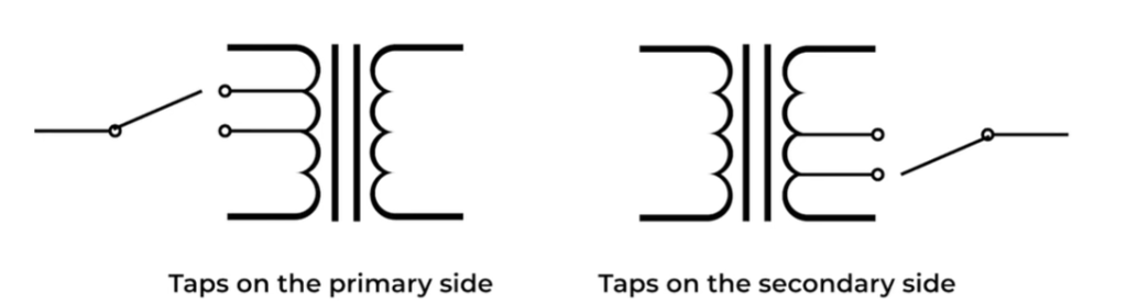
Their location depends on transformer application and design.
There are two major types of tap changers:
- Off-load tap changer
- On-load tap changer
Off-load tap changers require complete shutdown before changing taps. Engineers manually change the tap position using a selector mechanism. Real-time voltage control is not possible here.
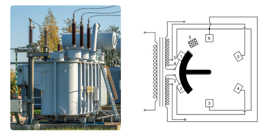
Tap steps may vary:
- 2%
- 3%
- 5%
The exact value depends on manufacturer and project requirement.
On-load tap changers work differently. These systems adjust taps automatically while the transformer remains energized. If voltage drops, the OLTC changes taps automatically and restores voltage.
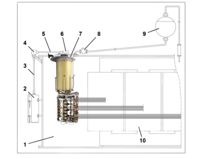
OLTC systems are more expensive but become necessary in critical applications. Proper maintenance also becomes very important because OLTC failure is a major cause of transformer failure.
Therefore, engineers must always check:
- Tap changer type
- Tap range
- Voltage regulation capability
while selecting transformers.
4. Cooling Methods of Transformer
Transformer life depends heavily on temperature. If temperature rises beyond safe limits, insulation life reduces rapidly. That is why cooling becomes one of the most important transformer parameters.
Even a 10% increase in temperature can reduce equipment life by nearly 50%. Therefore, cooling is not just about comfort. It directly affects transformer reliability and lifespan.
Transformers commonly use different cooling methods represented by codes such as:
- ONAN
- ONAF
- OFAF
- OFWF
ONAN means:
- Oil Natural
- Air Natural
In this method, oil circulates naturally inside the transformer. Air also cools the radiator naturally without fans or pumps. This method commonly suits smaller transformers and controlled environments.
ONAF means:
- Oil Natural
- Air Forced
Here, oil still moves naturally. However, fans force air through radiators for better cooling.
Some transformers may have dual ratings. For example:
- 20 MVA with ONAN
- 25 MVA with ONAF
Without fans, the transformer handles 20 MVA safely. With fans operating, loading increases to 25 MVA.
OFAF means:
- Oil Forced
- Air Forced
Here, pumps circulate oil actively while fans cool the radiators.
OFWF means:
- Oil Forced
- Water Forced
This method uses water cooling for heavily loaded transformers and large power ratings.
Many transformers also use staged cooling control. When temperature rises:
- First fan group starts
- Additional fan groups activate later
- Alarm may operate at higher temperature
- Tripping may occur if temperature rises excessively
That is why transformer temperature monitoring becomes extremely important.
5. Transformer Impedance
Transformer impedance directly affects the short circuit level of the system. This value usually appears on the transformer nameplate as:
- 5%
- 6%
- 10%
- 12%
In AC systems, impedance represents total opposition to current flow. It includes:
- Resistance
- Inductive reactance
- Capacitive reactance
Transformer impedance becomes extremely important during short circuit conditions.
Suppose a short circuit occurs on the secondary side. If transformer impedance is very low, short circuit current becomes extremely high because opposition to current remains low.
Now consider another transformer with much higher impedance. In that case, short circuit current becomes lower because current faces greater opposition.
However, choosing very high impedance is also not the correct solution. Higher impedance increases:
- Voltage drop
- Poor voltage regulation
Therefore, engineers must find the correct balance between:
- Acceptable voltage drop
- Acceptable short circuit level
This parameter directly affects equipment selection because:
- Circuit breakers
- Disconnectors
- Protection devices
must withstand and interrupt the expected fault current safely.
That is why transformer impedance becomes one of the most critical parameters during system design.
Conclusion
Transformer parameters help engineers understand whether two transformers are truly similar or not. Even transformers with identical voltage and MVA ratings may behave differently because of vector groups, losses, tap changers, cooling methods, and impedance values.
These parameters also affect voltage regulation, efficiency, parallel operation, transformer life, and short circuit performance.
Understanding them properly helps engineers select the right transformer for every application.
For a clearer and more practical understanding, it is recommended to watch the full video explanation.

