
What Are The Key Parameters of CT?
What Are The Key Parameters of CT? https://www.theelectricalguy.in/wp-content/uploads/2026/02/maxresdefault-2-2-1024x576.jpg 1024 576 Gaurav Joshi https://secure.gravatar.com/avatar/f6a3006f3f7233a71d79d0e705c167ae12516870e5239627478665ae377435b3?s=96&d=mm&r=gIn this article, we will discuss the most important Parameters of CT that every electrical engineer must know. These parameters often appear in technical interviews. They also play a major role in real power system applications.
If you understand these five key points clearly, you can confidently answer most CT-related questions. We will cover rated secondary current, rated extended current rating, accuracy classes, accuracy limit factor, and instrument safety factor. Each concept is simple when explained step by step.
Let us begin with the first parameter.
Table of Content
- Rated Secondary Current
- Rated Extended Current Rating
- Accuracy Classes of CT
- Accuracy Limit Factor (ALF)
- Instrument Safety Factor (ISF)
- Conclusion
Rated Secondary Current – One of the Most Important Parameters of CT
When you look at a current transformer nameplate, you will see two current values. One is the rated primary current. The other is the rated secondary current. The rated primary current is the current flowing through the primary conductor. This is the actual system current. The rated secondary current is the output current available at the CT secondary terminals.
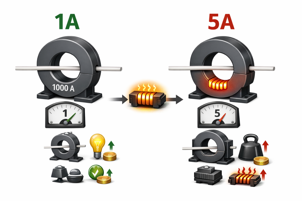
Typically, the secondary current is either 1 ampere or 5 ampere. Some countries also use 2 ampere, but this is less common. Today, there is a clear trend toward using 1 ampere as the secondary rating. Why is 1 ampere preferred? The answer lies in I²R losses. When current increases, I²R losses increase significantly. A 5 ampere secondary produces much higher losses compared to 1 ampere. In fact, the loss increases proportionally with the square of the current.
Higher losses mean higher burden on the CT. That makes the core heavier and more expensive. Therefore, 1 ampere secondary current reduces losses, reduces burden, and improves efficiency. On the nameplate, you will often see something like 1000/1 A. This means the primary current is 1000 ampere and the secondary current is 1 ampere.
Among all the Parameters of CT, this one is frequently asked in interviews. If someone asks which is better, 1 A or 5 A, you now know the logic behind the answer.
Rated Extended Current Rating in Parameters of CT
Next, let us discuss the rated extended current rating. Suppose a CT has a rated primary current of 1000 ampere. This means it can carry 1000 ampere continuously without thermal issues. The temperature rise will remain within standard limits.
However, in real systems, current does not always remain constant. Sometimes, due to overload or abnormal conditions, the current may increase. The CT must handle this increase without overheating.
That is where rated extended current rating becomes important. You may see values such as 120%, 150%, or 200% mentioned on the nameplate. If it is marked as 120%, it means the CT can carry 120% of rated current continuously without exceeding temperature limits. So, for a 1000 ampere CT, it can carry 1200 ampere safely.
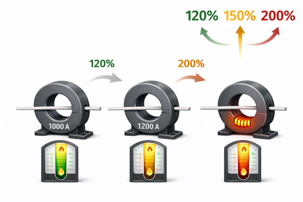
Similarly, if it is 200%, the CT can carry 2000 ampere continuously while maintaining acceptable temperature rise. This parameter ensures thermal stability during unstable system conditions. It is especially important in networks where load fluctuates frequently.
Accuracy Classes in Parameters of CT
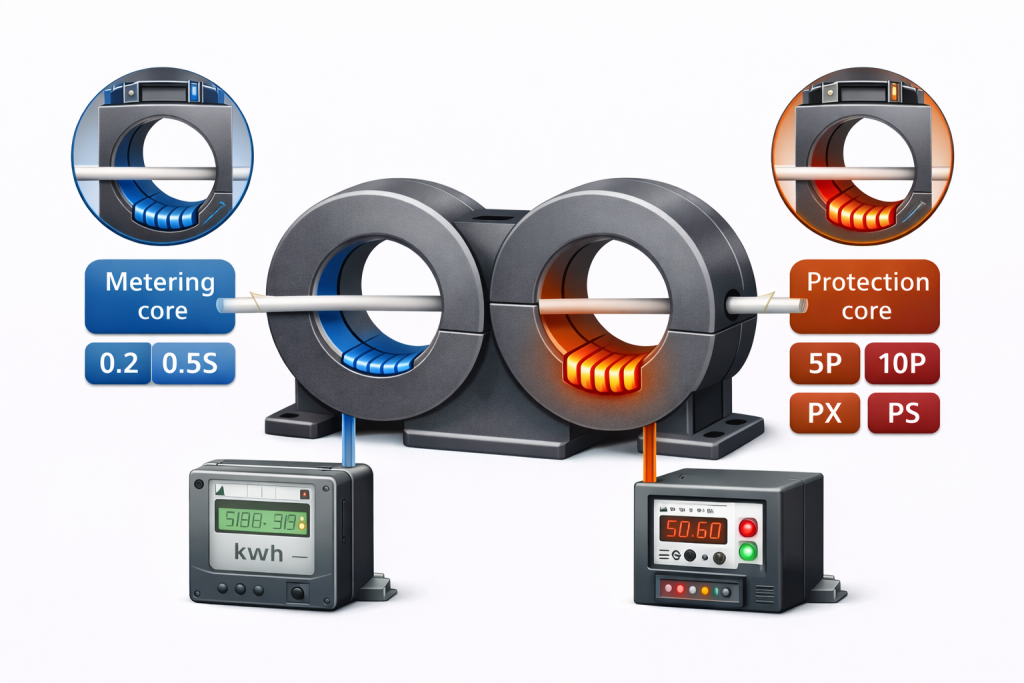
Another crucial part of Parameters of CT is accuracy class. A current transformer serves two purposes. First, it measures current for metering. Second, it supplies current to protection relays. Because of these two functions, CTs have two types of cores. One core is dedicated to metering. The other core is dedicated to protection.
Metering accuracy classes include 0.2, 0.2S, 0.5, and 0.5S. Among these, 0.2 and 0.2S are commonly used for revenue metering. These classes are highly accurate. Protection accuracy classes include 5P and 10P. There are also special classes like PX or PS used in specific protection schemes.
Each class has different characteristics. Metering cores focus on precise measurement at normal load. Protection cores focus on performance during fault conditions. A CT may have multiple cores. It can have one metering core and several protection cores. The exact number depends on system requirements.
The design of each core differs because their operating conditions differ. Therefore, accuracy classes form a critical part of the Parameters of CT.
Accuracy Limit Factor (ALF)
Now let us understand the accuracy limit factor. This factor applies only to protection cores such as 5P and 10P. It does not apply to metering cores. Suppose a CT has a rated primary current of 1000 ampere. During a fault, this current can increase sharply. The protection relay must detect this high current correctly.
If the CT saturates during fault, the relay will not receive accurate current. That may lead to failure in fault clearing. Accuracy Limit Factor ensures that the CT does not saturate up to a specific multiple of rated current. For example, if the class is 5P10, the number 10 indicates the ALF. It means the CT will maintain accuracy up to 10 times rated current.
So, if rated current is 1000 ampere, the CT will remain accurate up to 10,000 ampere. Similarly, 5P20 means the CT will maintain performance up to 20 times rated current. Higher ALF means better fault performance. However, it also increases cost and size. Therefore, ALF defines the fault current handling capability of protection cores.
Instrument Safety Factor (ISF)
The last important parameter is Instrument Safety Factor. ISF is applicable only to metering cores. It is not required for protection cores. Interestingly, ISF works opposite to ALF. ALF ensures that CT does not saturate. In contrast, ISF ensures that CT saturates quickly during high current.
Why is this required?
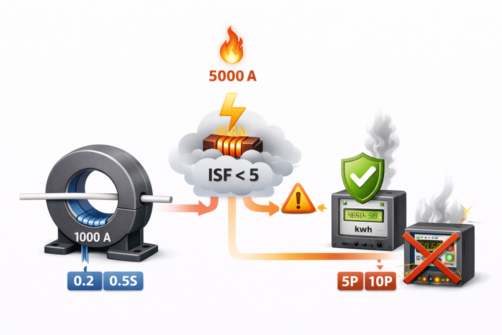
Meters are not designed to carry high current. If a severe fault occurs and high current reaches the meter, it may damage the device. To protect the meter, the CT must saturate before excessive current reaches the secondary circuit. For example, if ISF is less than 5, it means the CT will saturate at 5 times rated primary current.
If rated current is 1000 ampere, saturation will occur around 5000 ampere. After saturation, secondary current will not increase proportionally. This protects the meter. Sometimes, ISF may be less than 10. Lower ISF means better safety for the meter. Thus, ISF ensures protection of metering equipment during abnormal system conditions.
Conclusion
Understanding the Parameters of CT is essential for both interviews and real-world work. These parameters explain how a CT behaves under normal and abnormal conditions.
Rated current ensures proper scaling. Extended rating ensures thermal safety. Accuracy class defines application. ALF supports protection reliability. ISF protects metering devices.
When you understand these five concepts clearly, CT nameplates become easy to interpret. Technical discussions also become simpler.
For better understanding, practical visuals and examples are very helpful. Watching the detailed video explanation will strengthen your clarity further. Keep learning and keep exploring electrical engineering concepts.
