
How Capacitive Voltage Transformer (CVT) works? Explained
How Capacitive Voltage Transformer (CVT) works? Explained https://www.theelectricalguy.in/wp-content/uploads/2025/10/maxresdefault-2-1024x576.jpg 1024 576 Gaurav Joshi https://secure.gravatar.com/avatar/f6a3006f3f7233a71d79d0e705c167ae12516870e5239627478665ae377435b3?s=96&d=mm&r=gCapacitive Voltage Transformers (CVTs) play a key role in high-voltage power systems. They safely measure and step down high voltages for metering, protection, and control purposes. In simple terms, a CVT makes it possible to take readings from transmission lines carrying thousands of volts while still keeping meters and relays protected from dangerous voltage levels. Moreover, by providing accurate and isolated voltage signals, CVTs ensure that power system monitoring and protection remain both safe and reliable.
Beyond just voltage measurement, CVTs also serve as coupling devices for power line carrier communication (PLCC), allowing data and communication signals to travel over the same transmission lines. Their design offers several advantages over traditional Inductive Voltage Transformers (IVTs), including cost efficiency, reduced size, and better performance at very high voltages.
In this article, we’ll explore what a CVT is, how it works, and why engineers prefer it over IVTs in modern power systems.
Table of Contents
- Understanding Voltage Transformers
- How Inductive Voltage Transformers Work
- Why Inductive Voltage Transformers Have Limitations
- Why Capacitive Voltage Transformers are Preferred
- Basic Working of a Capacitive Voltage Transformer
- How Voltage Division Happens in CVT
- Using an Auxiliary Transformer
- The Role of Insulation and the Electromagnetic Unit
- Correcting the Phase Angle Problem
- Avoiding Electrical Resonance in CVTs
- The Construction of a CVT
- Advantages of Using a CVT
- CVT in Power Line Carrier Communication
- How CVTs Replace Coupling Capacitors
- When Wave Traps Are Not Used
- The Principle Behind CVT Operation
- The Dual Role of a CVT
- Why CVTs Dominate High Voltage Applications
- Summary
- Conclusion
Understanding Voltage Transformers
There are two main types of voltage transformers:
- Inductive Voltage Transformer (IVT)
- Capacitive Voltage Transformer (CVT)
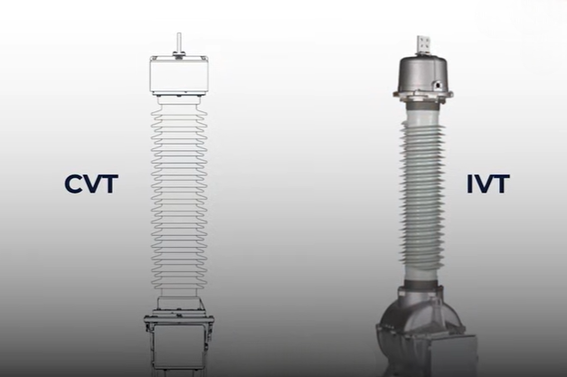
For high and extra-high voltage systems, typically 145 kV and above, CVTs are more popular. They offer several benefits over IVTs, making them dominant in this voltage range.
How Inductive Voltage Transformers Work
Inductive Voltage Transformers work like regular power transformers. Their principle is electromagnetic induction. They have an iron core, primary winding, and secondary winding.
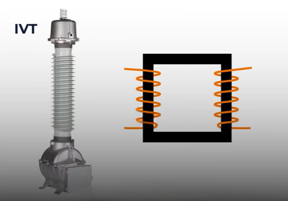
This setup works well up to certain voltage levels, such as 12 kV or 36 kV. However, as voltage increases beyond 245 kV, 420 kV, or 800 kV, problems start to appear.
Why Inductive Voltage Transformers Have Limitations
As the voltage increases, the core size must increase too. This adds bulk and weight. The insulation also needs to be stronger to prevent breakdowns, which again makes the device larger and heavier.
For example, a 400 kV IVT would be enormous compared to a 36 kV transformer. The materials inside core, insulation, and windings, all become heavier and thicker.
Moreover, increased material and insulation lead to higher losses. These transformers become inefficient and impractical for very high voltages. Hence, we usually limit IVTs to 145 kV and rarely use them even at 245 kV.
Why Capacitive Voltage Transformers are Preferred
The problems with IVTs led to the use of Capacitive Voltage Transformers for high and extra-high voltages. CVTs solve the size, cost, and insulation issues efficiently.
A CVT operates on two basic principles:
- Voltage division by capacitors
- Electromagnetic induction
Basic Working of a Capacitive Voltage Transformer
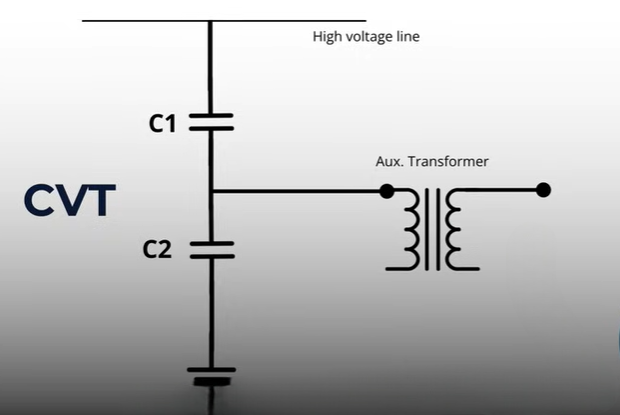
As the name suggests, a Capacitive Voltage Transformer includes capacitors. It uses a capacitor stack usually two capacitors, C1 and C2 connected in series across the high-voltage line.
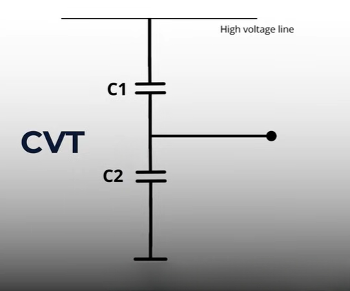
When capacitors are connected in series, the voltage divides between them. The voltage across each capacitor depends on their capacitance values.
How Voltage Division Happens in CVT
To understand voltage division, consider a simple example. Suppose a 10-volt source is connected to two capacitors in series. The voltage across each capacitor divides based on their capacitance.
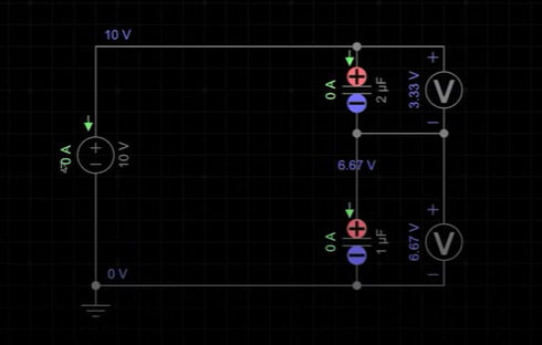
If both capacitors have different values, their voltage distribution will change. The smaller the capacitance, the higher the voltage across it. This same concept is applied in CVTs.
In a CVT, the capacitors C1 and C2 divide the total high voltage, and the circuit taps a reduced voltage from their junction.
Using an Auxiliary Transformer
However, the divided voltage at this point is still too high. It could be in kilovolts, not the low level needed by meters or relays (which work at 110 V or 220 V).
To reduce it further, a small auxiliary transformer is used. This transformer takes the intermediate voltage from the capacitor divider and steps it down to the standard secondary voltage, usually 110/√3 or 220/√3 volts.
This step introduces electromagnetic induction into the process, completing the dual principle of the CVT: capacitive voltage division and induction-based transformation.
The Role of Insulation and the Electromagnetic Unit
The auxiliary transformer requires strong insulation because it connects to relatively high voltages. Engineers place it inside a metal tank filled with insulating oil.
This tank, positioned at the bottom of the CVT, is called the Electromagnetic Unit (EMU). It houses the auxiliary transformer and provides both insulation and protection.
Correcting the Phase Angle Problem
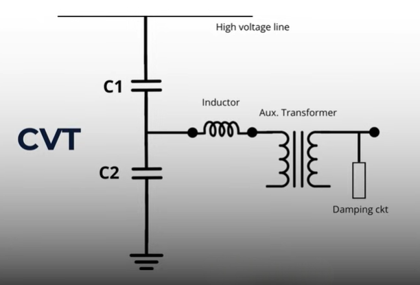
When a resistive load, such as a meter, connects to the CVT output, a phase angle issue arises. The capacitor introduces a phase shift, causing errors.
To correct this, an inductor is added to the circuit. The inductive reactance balances the capacitive reactance, aligning the phase angle correctly.
This balance ensures that the CVT can now supply accurate voltage signals to connected meters and relays.
Avoiding Electrical Resonance in CVTs
Introducing both capacitors and inductors in one circuit can create another issue, electrical resonance.
At a certain frequency, the inductive and capacitive effects can cancel each other, producing a low-impedance path. This can cause core saturation, overheating, and even damage to the transformer.
To prevent this, engineers add a damping circuit inside the electromagnetic unit. It stops resonance and ensures stable operation.
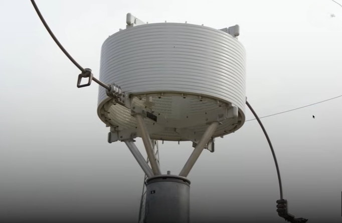
The Construction of a CVT
Let’s understand the actual structure of a CVT.
At the top, there is a high-voltage terminal connected to the transmission line. Just below it, you’ll notice the visible insulator section made of porcelain or silicon composite, which carefully houses the capacitor stack. Here, multiple small capacitors are connected together to form C1 and C2, ensuring proper voltage division and insulation.
Moving downward, at the bottom, you’ll find the tank, which contains the auxiliary transformer, reactor, and damping circuit, all immersed in oil for proper insulation and cooling. Finally, the terminal box located outside this unit connects to meters, relays, or protection devices, ensuring smooth monitoring and protection of the system.
Advantages of Using a CVT
The biggest advantage of a Capacitive Voltage Transformer is its compact size. Compared to a similar-rated IVT, a CVT is smaller, lighter, and easier to install.
Because of reduced core material and insulation, CVTs are also cost-effective and energy-efficient. But there’s one more major benefit they can help in Power Line Carrier Communication (PLCC) systems.
CVT in Power Line Carrier Communication
High-voltage transmission lines don’t only carry power. They also carry communication signals at high frequencies typically 50 kHz to 500 kHz.
These communication signals must not enter the substation, as they can interfere with transformers and other equipment.
To stop this, a wave trap (or line trap) is used. It blocks high-frequency communication signals and allows only the 50/60 Hz power signal to pass through.
However, the signal still needs a path to reach the communication equipment even after being blocked. Coupling capacitors provide this path by allowing high-frequency signals to travel to PLCC devices through their low impedance.
How CVTs Replace Coupling Capacitors
When a CVT is installed along with a wave trap, it can perform the same role as a coupling capacitor. The capacitors inside the CVT allow the high-frequency communication signals to pass to PLCC equipment.
This means we don’t need separate coupling capacitors anymore. The CVT performs two functions voltage transformation and signal coupling with a single device.
This dual functionality saves both cost and space, making CVTs an ideal choice for high-voltage substations.
When Wave Traps Are Not Used
If a system doesn’t use Power Line Carrier Communication, then a CVT works only as a voltage transformer. In that case, the wave trap is not required.
Even without communication signals, the CVT still performs accurate voltage measurement and protection duties efficiently.
The Principle Behind CVT Operation
To summarize, the working principle of a Capacitive Voltage Transformer is simple:
- It first uses capacitive voltage division to reduce the high voltage.
- Then, an auxiliary transformer applies electromagnetic induction to step down the voltage to a safe, measurable level.
Together, these processes allow CVTs to work effectively in high-voltage environments where inductive transformers are not practical.
The Dual Role of a CVT
When combined with a wave trap, a CVT also functions as a Coupling Capacitor Voltage Transformer (CCVT). The term CCVT simply reflects this dual role coupling for communication and voltage transformation.
So, whether you call it CVT or CCVT, the device serves both measurement and communication needs in high-voltage systems.
Why CVTs Dominate High Voltage Applications
CVTs dominate high and extra-high voltage networks because they are:
- Compact and lightweight
- Cost-effective
- Reliable and efficient
- Able to serve dual purposes (voltage transformation and communication coupling)
These advantages make them essential in modern power transmission systems.
Summary
To recap:
- IVTs work on electromagnetic induction and are suitable up to 145 kV.
- CVTs use both capacitive voltage division and electromagnetic induction, making them ideal for 245 kV and above.
- CVTs are smaller, cheaper, and can assist in Power Line Carrier Communication.
- The main components include capacitor stacks (C1 and C2), auxiliary transformer, reactor, and damping circuit, all working together inside the electromagnetic unit.
Conclusion
A Capacitive Voltage Transformer (CVT) is an advanced and efficient solution used for high-voltage measurement and protection. Compared to traditional inductive transformers, it offers several advantages. Its compact design, cost-effectiveness, and built-in communication capabilities make it a preferred choice in modern power systems.
Moreover, a CVT not only reduces installation space but also enhances system reliability and monitoring. Because of these benefits, substations and transmission networks widely use it where precision and stability are essential.
For a clearer and more visual understanding of how a CVT works, including its internal construction and operating principle, watch the original YouTube video, “Capacitive Voltage Transformers (CVTs): Working Explained.” The video carefully walks you through each component and explains how theory connects with real-world applications, making the concept easy to grasp and apply.
