
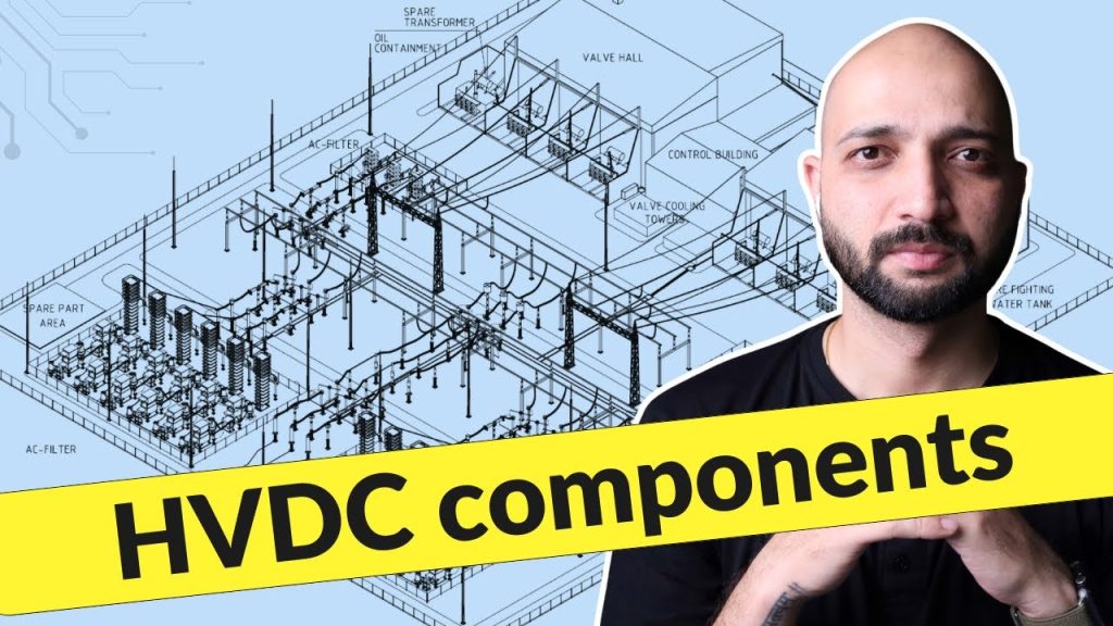
What Are the Components of HVDC Transmission System? Explained Simply
What Are the Components of HVDC Transmission System? Explained Simply https://www.theelectricalguy.in/wp-content/uploads/2026/01/maxresdefault-1-1-1024x576.jpg 1024 576 Gaurav Joshi https://secure.gravatar.com/avatar/f6a3006f3f7233a71d79d0e705c167ae12516870e5239627478665ae377435b3?s=96&d=mm&r=gHigh Voltage Direct Current transmission is becoming important in modern power systems. In specific situations, it offers clear advantages over traditional AC transmission. However, HVDC is not a simple setup. It requires several carefully designed components working together. Each component plays a defined role in converting, protecting, and transmitting power.
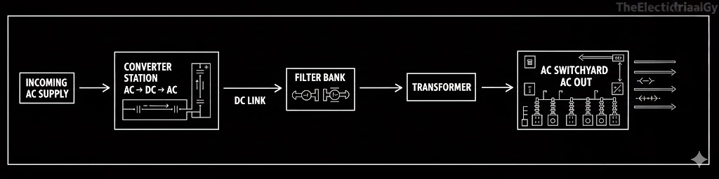
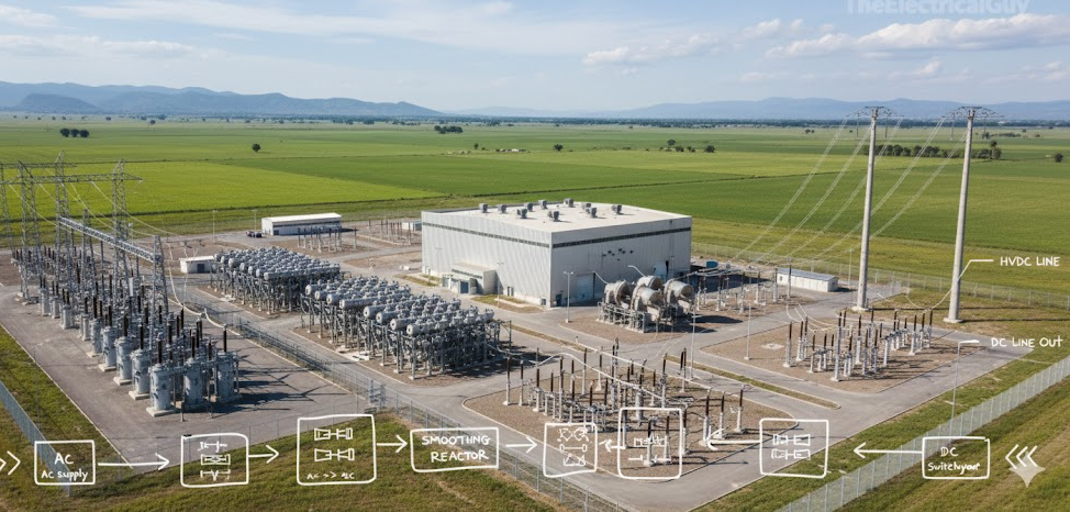
When people think about HVDC transmission, a simple picture usually appears. AC power enters a station, converts into DC, travels through a DC line, and then converts back into AC. After that, normal AC transmission continues. While this idea is correct, it only shows part of the system. In reality, many supporting components make this process possible and reliable.
To understand HVDC clearly, it is important to follow the system flow step by step. This explanation starts from the incoming AC supply and moves through each stage, just like the actual transmission process.
Table of Contents
- Incoming AC Supply and AC Switchyard
- Converter Transformer and Converter Station
- DC Output, Smoothing Reactor, and DC Switchyard
- Receiving Station and Conversion Back to AC
- Overall Flow of HVDC Transmission System Components
- Conclusion
Incoming AC Supply and AC Switchyard
Every HVDC system begins with an incoming AC supply. This supply usually comes from an existing AC transmission network. Before this power reaches the converter station, it must pass through protection equipment. Faults can occur at any time in an AC system. When a fault happens, current can rise to a very high value. Without protection, this can damage equipment.
To handle this, an AC switchyard is installed at the entry point. The AC switchyard contains all the essential substation equipment needed to protect the system. Its main role is to isolate faults and protect expensive components downstream. It also allows operators to safely control and disconnect the supply when required.
The AC switchyard includes standard substation elements such as circuit breakers, disconnectors, current transformers, voltage transformers, and lightning arresters. These devices ensure safe operation during both normal and abnormal conditions. Along with protection, power quality is also addressed at this stage.
The incoming AC supply may contain harmonics. These harmonics reduce efficiency and affect system performance. To manage this, AC filters are connected within the switchyard. These filters reduce harmonic content and help balance reactive power. After filtering, the AC output becomes cleaner and more stable. This improved AC supply then moves toward the conversion stage.
Converter Transformer and Converter Station
Even after filtering, the AC voltage level remains very high. In many systems, this voltage can reach around 420 kV. Such a high voltage cannot be directly supplied to the converter station. Voltage adjustment and phase control are required before conversion.
This task is handled by the converter transformer. The converter transformer steps down the voltage to a level suitable for the converter. It also adjusts the phase angle of the AC supply. Phase adjustment depends on the converter technology being used. This makes the power compatible with the conversion process.
The converter transformer is one of the largest and most expensive components in the HVDC system. It is bulky, heavy, and produces significant noise during operation. Because of its cost and importance, it requires strong protection from the AC switchyard.
Once the voltage and phase are properly adjusted, the AC supply enters the converter station. This is where the actual conversion from AC to DC takes place. Different technologies are available for this purpose. One commonly used method involves thyristor-based converters.
During operation, the converter station generates a large amount of heat. Heat buildup can affect performance and damage components. For this reason, cooling arrangements are always required. The type of cooling depends on the converter technology, but cooling is essential in all cases.
Dedicated cooling systems are installed to manage this heat. These systems help maintain safe operating temperatures. The converter station is always housed inside a building. Outdoor installation is not suitable due to safety and environmental requirements. Once conversion is complete, DC power moves to the next stage.
DC Output, Smoothing Reactor, and DC Switchyard
The DC output from the converter station is not perfectly smooth. It contains ripples, which affect power quality. These ripples can reduce efficiency and create stress on the DC transmission system. To improve the DC output, a smoothing reactor is added.
The smoothing reactor plays multiple roles in the HVDC system. It smooths the DC waveform and reduces ripple content. It also helps limit DC fault current, which is important for system protection. In addition, it reduces the effect of harmonics present on the DC side.
Different designs are available for smoothing reactors. Common options include oil-immersed reactors and air-core reactors. Regardless of the design, the function remains the same. After passing through the smoothing reactor, the DC output becomes more stable and suitable for long-distance transmission.
Even after smoothing, protection is still necessary. Faults can occur on the DC side as well. Maintenance activities may also require isolation of equipment. To handle these situations, a DC switchyard is installed.
The DC switchyard contains DC switchgear and protective devices. It includes switches, disconnectors, instrument transformers, and lightning arresters. These components protect the DC system from faults and allow safe operation. Similar to the AC side, both air-insulated and gas-insulated switchgear options are available for DC systems.
From the DC switchyard, power enters the HVDC transmission line. This line carries DC power over long distances with lower losses compared to AC transmission. At this point, the sending-end process is complete.
Receiving Station and Conversion Back to AC
At the receiving end, the HVDC system follows a similar structure in reverse order. The DC transmission line first connects to a DC switchyard. This switchyard protects receiving-end equipment from DC faults. A smoothing reactor may also be present here to further stabilize the DC supply.
After protection and smoothing, DC power enters the converter station at the receiving end. Here, DC is converted back into AC. The same converter technologies support this reverse conversion process. Conversion again takes place inside a controlled indoor environment.
Once DC converts into AC, the power passes through a converter transformer. This transformer adjusts the voltage to match the receiving AC network. Phase alignment is also ensured to allow smooth integration with the grid.
The converted AC then enters the AC switchyard. This switchyard provides protection, control, and isolation, just like on the sending side. If required, AC filters can also be installed here to reduce harmonics and improve power quality.
From the AC switchyard, power is supplied to the AC transmission network. The electricity then flows to substations and consumers as normal AC power. With this, the HVDC transmission cycle is complete.
Overall Flow of HVDC Transmission System Components
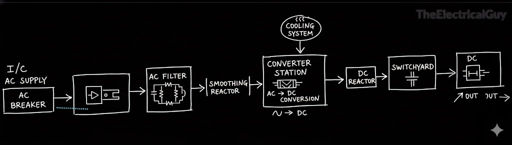
The HVDC transmission system follows a clear and logical sequence. Power enters as AC, undergoes protection and filtering, converts into DC, travels through a DC line, and then converts back into AC. Each stage uses specific components to ensure safety, efficiency, and reliability.
At a broader level, the main components involved are:
- Incoming AC supply and AC switchyard
- Converter transformer
- Converter station with cooling arrangement
- Smoothing reactor
- DC switchyard
- HVDC transmission line
- Receiving-end components in reverse order
While specific designs may vary based on technology, this general structure remains consistent. Understanding this flow helps simplify an otherwise complex system.
Conclusion
HVDC transmission is a powerful solution for specific power transmission needs. Although the system is complex, each component has a clear purpose. When these components work together, they enable safe and efficient long-distance power transfer.
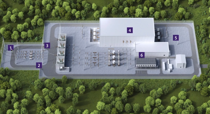
A visual explanation always improves understanding. The referenced video shows the HVDC layout using a 3D model. Watching it will provide better clarity and practical insight into the system components.
