
Why Current Transformer Secondary Must Never Be Open-Circuited
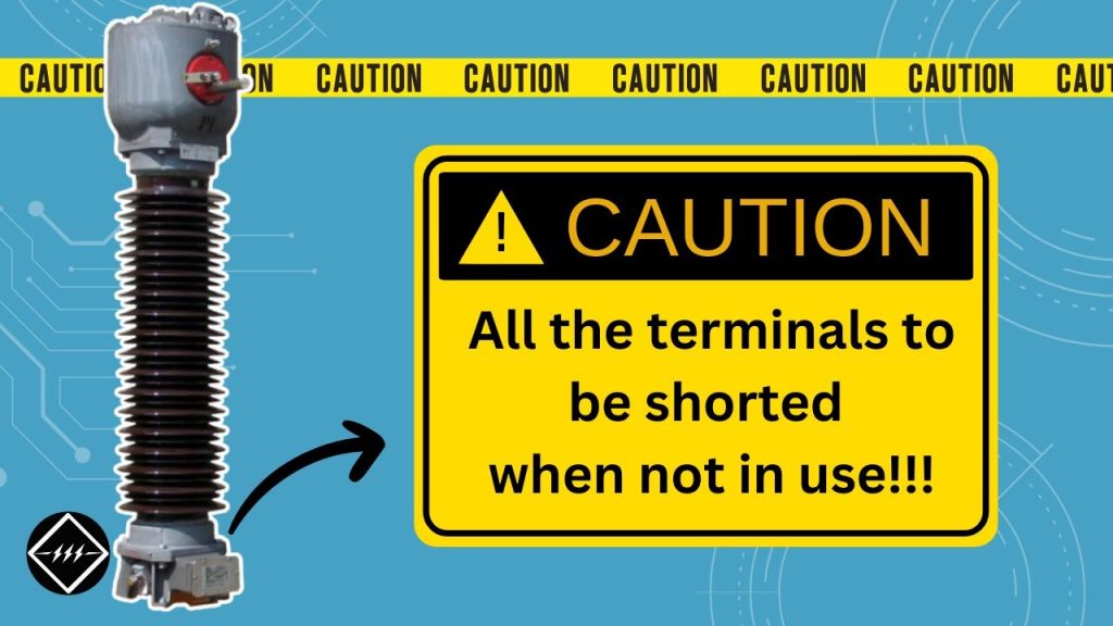
Why Current Transformer Secondary Must Never Be Open-Circuited https://www.theelectricalguy.in/wp-content/uploads/2026/02/maxresdefault-3-1024x576.jpg 1024 576 Gaurav Joshi https://secure.gravatar.com/avatar/f6a3006f3f7233a71d79d0e705c167ae12516870e5239627478665ae377435b3?s=96&d=mm&r=gIf you have ever checked a current transformer nameplate, you would have seen a clear warning. It says all secondary terminals must be shorted when not in use. This instruction is not optional. It is a serious safety requirement.
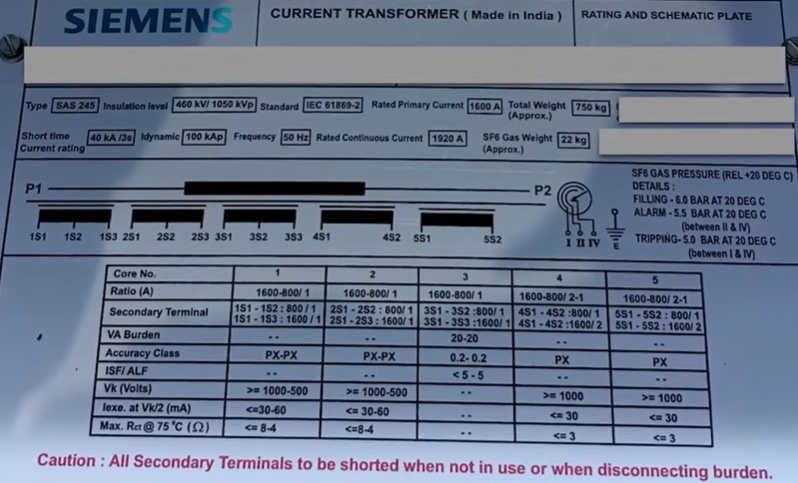
Ignoring this rule can cause insulation failure, fire, or even explosion. More importantly, it can put lives at risk. In this article, we will clearly understand why current transformer secondary must never be open-circuited. To understand the open circuit current transformer properly, we must first revisit the working principle.
Table of Contents
- Understanding the Working Principle Before Exploring Why Current Transformer Secondary Must Never Be Open-Circuited
- How Current Transformer Operation Differs from a Power Transformer
- Primary and Secondary Behavior in a Current Transformer
- Why Current Transformer Secondary Must Never Be Open-Circuited: Core Saturation Explained
- Practical Example: Normal Operating Condition
- Practical Example: Open-Circuited Secondary Condition
- Dangers When Current Transformer Secondary Is Open
- The Real Technical Reason Behind Why Current Transformer Secondary Must Never Be Open-Circuited
- Why Short-Circuiting the Secondary Is Safe
- Comparison: Power Transformer vs Current Transformer Behavio
- What Happens Inside the Core During Open Circuit
- Important Safety Practice for Engineers
- Summary: Why Current Transformer Secondary Must Never Be Open-Circuited
- Conclusion
Understanding the Working Principle Before Exploring Why Current Transformer Secondary Must Never Be Open-Circuited
Before we answer the main question, we need to review how a transformer works. For simplicity, let us consider a regular power transformer.
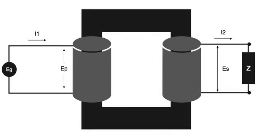
A transformer works on Faraday’s law of electromagnetic induction. It has a primary winding and a secondary winding. When we apply supply to the primary, current flows. This current produces magnetomotive force.
Flux Creation in a Regular Transformer
When primary current flows, it creates flux in the core. This flux is denoted as Φ1. Some part of this flux links to the secondary winding. That linked part is mutual flux. The rest is leakage flux.
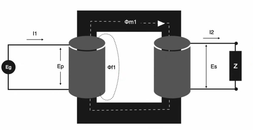
When we connect the secondary load, secondary current starts flowing. This current produces its own flux, denoted as Φ2. The flux produced by the secondary opposes the primary flux.
As a result, the net flux inside the core becomes:
Φm = Φ1 – Φ2
This mutual flux Φm induces secondary voltage. In a regular transformer, primary current depends on secondary current. When the load increases, primary current increases. When the load reduces, primary current reduces.
That dependency keeps the flux balanced.
How Current Transformer Operation Differs from a Power Transformer
Now let us move toward the current transformer. The construction looks similar at first. However, there is a critical difference.
A current transformer has only one dedicated winding. That is the secondary winding. The primary winding is simply the conductor passing through the core.
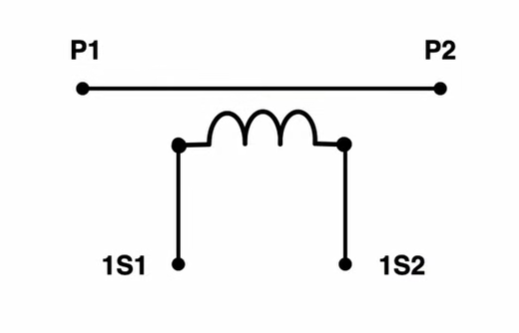
In most cases, this conductor is part of a transmission line. Therefore, the power system determines the current flowing through it. It does not depend on the CT.
Series Connection Concept
Engineers connect a current transformer in series with the system. Because of this, primary current always flows. It does not matter whether the secondary has a load connected or not.
This is the biggest difference between a power transformer and a current transformer.
In a power transformer:
- Primary current depends on secondary load.
In a current transformer:
- Primary current is independent of secondary load.
This difference creates the risk.
Primary and Secondary Behavior in a Current Transformer
Let us analyze the flux behavior inside a CT.
When primary current flows, it produces flux Φ1. If the secondary is connected to a load, secondary current flows. That current produces opposing flux Φ2.
Therefore, the net flux becomes:
Φm = Φ1 – Φ2
This net flux remains controlled. As long as Φ2 exists, it balances Φ1.
However, if the secondary is open-circuited, no secondary current flows. That means Φ2 becomes zero. Now the net flux becomes:
Φm = Φ1
There is no opposing flux. Therefore, the entire primary flux remains inside the core. This condition leads to serious consequences.
Why Current Transformer Secondary Must Never Be Open-Circuited: Core Saturation Explained
When the secondary is open, primary current still flows. Because the CT is connected in series, you cannot stop that current.
Since there is no secondary current, no opposing flux exists. Therefore, the core flux rises sharply.
This high flux pushes the core into saturation. When the core saturates, magnetic properties degrade. At the same time, very high voltage appears across the secondary terminals.
That voltage is extremely dangerous.
Practical Example: Normal Operating Condition
Let us understand this with numbers.
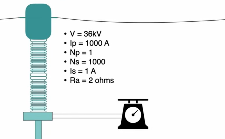
Assume a 36 kV transmission line. The primary current is 1,000 A. The primary has one turn. The secondary has 1,000 turns.
The secondary current is 1 A. Suppose the connected meter has 2 ohms resistance.
Voltage across the meter equals:
V = I × R
V = 1 × 2
V = 2 volts
Under normal operation, the voltage across the secondary is only 2 volts. This is safe. The insulation easily handles this value. Everything remains stable because secondary current flows and balances flux.
Practical Example: Open-Circuited Secondary Condition
Now remove the meter. The secondary becomes open. Primary current is still 1,000 A. Secondary current becomes zero. Therefore, no opposing flux exists.
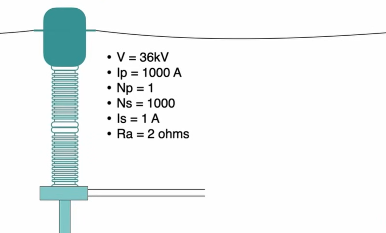
Now calculate secondary voltage using transformation ratio. Voltage ratio equals turns ratio.
Vp / Vs = Np / Ns
Rearranging:
Vs = (Vp × Ns) / Np
Vp = 36,000 volts
Ns = 1,000
Np = 1
Vs = 36,000 × 1,000
Vs = 36,000,000 volts
This is 36,000 kV. This value is extremely high. Even if practical limits reduce it, the voltage is still dangerous. This voltage can break insulation instantly.
Dangers When Current Transformer Secondary Is Open
When the secondary is open-circuited, several serious problems occur:
- Core saturation
- Extremely high secondary voltage
- Insulation breakdown
- Risk of fire
- Risk of explosion
- Severe danger to personnel nearby
High voltage stresses insulation beyond its rating. Eventually, insulation fails. When insulation fails, arcing may occur. Arcing can lead to fire. If someone is working nearby, the situation becomes life-threatening. That is why the warning exists on every CT nameplate.
The Real Technical Reason Behind Why Current Transformer Secondary Must Never Be Open-Circuited
The root cause is flux imbalance.
When secondary current flows, it produces counter flux. That counter flux limits the net core flux.
When secondary is open, counter flux disappears. As a result:
- Net flux equals primary flux
- Core saturates
- High induced voltage appears
The CT is not designed to withstand such high secondary voltage. Therefore, insulation fails.
This condition does not exist in power transformers. In a power transformer, if the secondary is open, primary current reduces to magnetizing current. That current is small.
However, in a CT, primary current remains full load current. That is the major difference.
Why Short-Circuiting the Secondary Is Safe
If you are not connecting any burden to the secondary, you must short it. When the secondary is shorted, current flows easily. That current produces opposing flux.
As a result, net flux remains low. Induced voltage remains low. Core remains unsaturated. Shorting the secondary protects the CT and protects people. This practice is standard across substations worldwide.
Comparison: Power Transformer vs Current Transformer Behavior
Let us summarize the difference clearly.
In a power transformer:
- Primary current depends on secondary load
- Open secondary results in small magnetizing current
- Flux remains limited
In a current transformer:
- Primary current does not depend on secondary
- Open secondary results in full primary flux
- Flux becomes excessive
- High voltage appears at secondary
This comparison explains why CT secondary must never be left open.
What Happens Inside the Core During Open Circuit
When secondary is open:
- Primary current produces magnetomotive force.
- Full flux builds inside the core.
- Core saturates quickly.
- High voltage is induced in secondary.
- Insulation experiences extreme stress.
The system is not stable in this state. The longer it remains open, the greater the risk.
Important Safety Practice for Engineers
Every engineer working in substations must remember this rule. Before disconnecting any relay or meter from a CT, first short the secondary terminals.
Never open the circuit directly. Most switchgear panels have shorting links. Always use them. Following this simple step prevents catastrophic failure.
Summary: Why Current Transformer Secondary Must Never Be Open-Circuited
Let us recap the key points. A current transformer operates on Faraday’s law. Its primary is connected in series. Therefore, primary current always flows.
When secondary carries current, it produces opposing flux. This keeps net flux under control. If the secondary is open-circuited, no opposing flux exists. Core flux becomes excessive. Core saturates. High voltage appears across secondary.
That high voltage damages insulation. It may cause fire or explosion. It may also endanger human life. For this reason, CT secondary must always be either connected to burden or shorted.
Conclusion
Understanding why current transformer secondary must never be open-circuited is essential for every electrical engineer. In fact, the risk is not theoretical. Instead, it is real and dangerous.
Basically, the entire problem arises due to flux imbalance and the series nature of CT connection. Once you clearly understand this principle, the warning on the nameplate begins to make complete sense.
Therefore, for a clearer visual explanation and a step-by-step technical breakdown, watch the full video. This will not only strengthen your understanding but also help you remember this critical safety concept.
