

What Is a CT Burden? Complete Guide to Current Transformer Burden Explained
What Is a CT Burden? Complete Guide to Current Transformer Burden Explained https://www.theelectricalguy.in/wp-content/uploads/2026/02/maxresdefault-1-1-1024x576.jpg 1024 576 Gaurav Joshi https://secure.gravatar.com/avatar/f6a3006f3f7233a71d79d0e705c167ae12516870e5239627478665ae377435b3?s=96&d=mm&r=gCT Burden is one of the most important concepts in current transformer performance. It directly affects measurement accuracy and protection reliability. Many engineers focus on ratios and classes but often overlook burden. This leads to serious system errors. Understanding CT Burden helps engineers design better protection and metering systems.
In this article, we will explain what CT Burden means, how it is formed, why it matters, and how it impacts accuracy. The explanation follows practical industry experience and standard guidelines.
Table of Contents
- Introduction to CT Burden in Current Transformers
- What Is a CT Burden?
- Applicability of CT Burden to Instrument Transformers
- IEC Definition of CT Burden
- Expression of CT Burden in Volt-Ampere
- Common Misconceptions About CT Burden
- Components That Form CT Burden
- Calculation of Total CT Burden
- Effect of CT Burden on Accuracy
- Practical Importance of CT Burden Selection
- Standard Burden Values in Modern Systems
- Conclusion
Introduction to CT Burden in Current Transformers
Current transformers convert high system current into a small measurable value. This reduced current flows through meters and relays. However, the CT never works alone. It always supplies current to connected equipment. These connected devices place an electrical load on the CT secondary.
This electrical load is called CT Burden. It is not a physical load. Instead, it represents the total impedance connected to the secondary circuit. Every device, wire, and connection contributes to this burden. Therefore, understanding this concept becomes essential for proper system operation.
What Is a CT Burden?
CT Burden refers to everything connected across the secondary terminals of a current transformer. This includes meters, relays, cables, and internal connections. All these elements together form an electrical load.
In simple terms, CT Burden is the total impedance seen by the secondary winding. When current flows through this impedance, voltage develops across it. This voltage directly influences transformer behavior. Therefore, burden determines how the CT performs under operating conditions.
Applicability of CT Burden to Instrument Transformers
The concept of burden is not limited to current transformers. It applies to all instrument transformers. This includes inductive voltage transformers and capacitive voltage transformers.

Every instrument transformer supplies power to external devices. These devices create electrical load. As a result, burden exists in every secondary circuit. The same principle applies across all types of instrument transformers. Hence, the explanation of burden remains valid for all of them.
IEC Definition of CT Burden
The International Electrotechnical Commission defines global technical standards. These standards guide transformer manufacturing and testing. For instrument transformers, IEC 61869-1 provides the main guidelines.
According to this standard, engineers define burden as the impedance or admittance of the secondary circuit. They express it in ohms or siemens along with power factor. However, the standard also states that engineers usually express burden in apparent power. They measure this apparent power in volt-ampere at rated current and power factor.
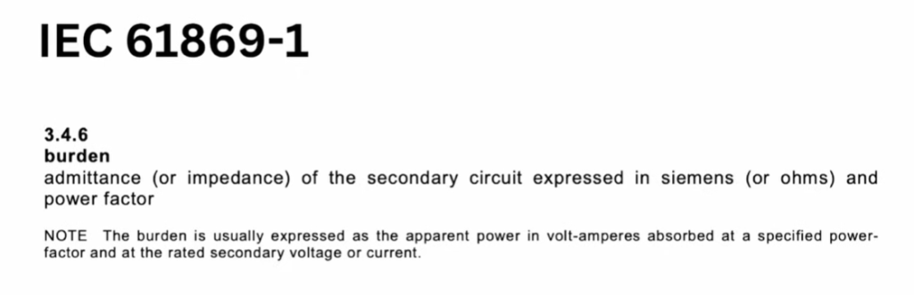
Therefore, in practice, engineers refer to burden in VA instead of resistance.
Expression of CT Burden in Volt-Ampere
In AC circuits, voltage and current continuously vary. Because of this, using resistance alone does not give a complete picture. Impedance and power become more meaningful parameters.
That is why CT Burden is expressed in volt-ampere. When a CT nameplate shows 10 VA, it means the transformer can supply 10 volt-ampere to connected equipment while maintaining accuracy.
This VA rating represents the maximum permissible burden. Exceeding this value affects performance. Staying far below it also reduces accuracy.
Common Misconceptions About CT Burden
Many engineers believe that only meters and relays create burden. This belief is only partially correct. These devices do contribute to burden. However, they are not the only contributors.
Several hidden elements also affect burden. These include winding resistance and long cable runs. Ignoring these factors leads to wrong calculations. As a result, CT performance suffers.
So, CT Burden includes visible and invisible electrical loads.
Components That Form CT Burden
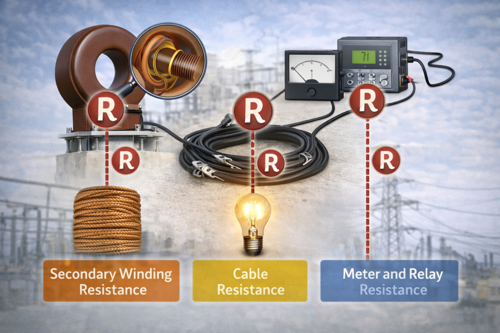
Resistance of CT Secondary Winding
The secondary winding of a CT is made from copper conductors. These conductors naturally have resistance. Internal joints and terminals also add resistance.
This resistance remains fixed and is specified by the manufacturer. During burden calculation, engineers must include this value. Ignoring winding resistance gives an incomplete burden estimate.
Resistance of Lead Wires
After leaving the CT terminal box, secondary current flows through long cables. These cables travel to control rooms where meters and relays are installed.
Longer cables have higher resistance. This resistance directly adds to CT Burden. In large substations, cable lengths can be significant. Therefore, cable resistance becomes a major contributor.
Secondary current rating also affects this resistance. Higher current increases I²R losses. That is why modern systems prefer 1-ampere secondaries. They reduce burden and power loss.
Resistance of Meters and Relays
Meters and relays consume electrical power. They draw current from the CT secondary. This creates electrical load.
Earlier mechanical devices required high power. As a result, older systems had very high burden ratings. Modern digital devices require very little power. Their resistance is low. Therefore, present-day burden values are much smaller.
This change has helped improve system efficiency and accuracy.
Calculation of Total CT Burden
Total CT Burden is obtained by combining all contributing resistances and impedances. Engineers must add winding resistance, cable resistance, and device resistance.
Only after combining these values can they determine the actual burden. If any component is ignored, the calculation becomes incorrect. Accurate estimation ensures proper CT selection and reliable operation.
Effect of CT Burden on Accuracy
CT accuracy strongly depends on burden. International standards guarantee accuracy only within a specific range.
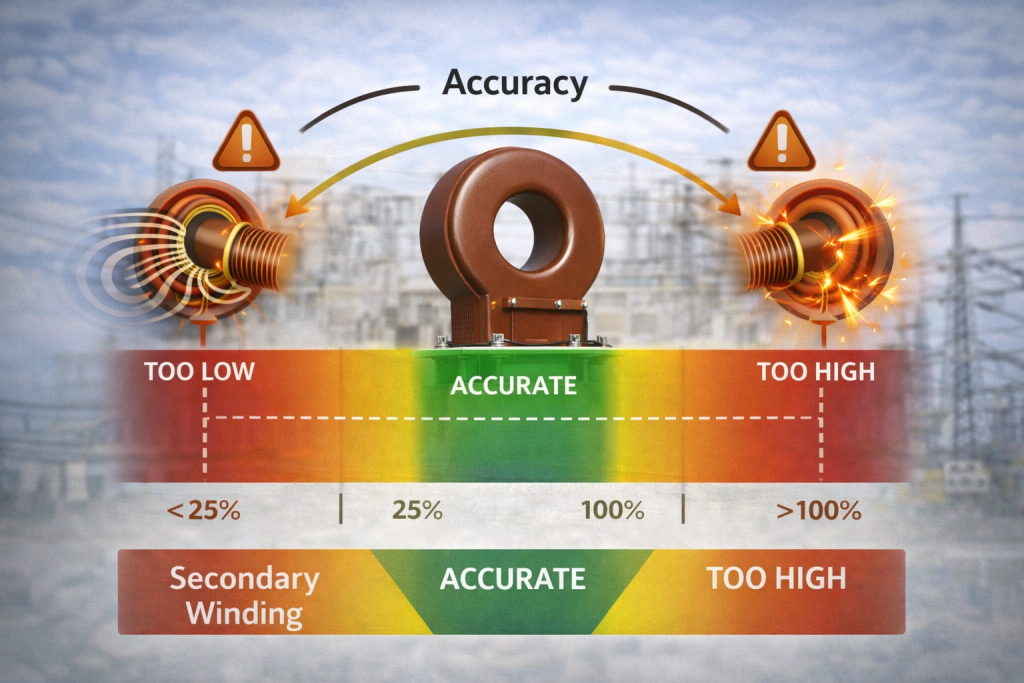
According to IEC, accuracy is guaranteed between 25% and 100% of rated burden. Outside this range, accuracy is not assured.
If burden is too high, the CT core may saturate. If burden is too low, magnetizing current increases. Both conditions reduce accuracy. Therefore, maintaining proper burden is critical.
Practical Importance of CT Burden Selection
Correct burden selection ensures reliable protection. Protection relays depend on accurate current signals. Wrong burden causes delayed or false tripping.
Metering systems also depend on accurate CT output. Incorrect burden produces wrong energy readings. This affects billing and system planning.
Therefore, burden selection directly impacts safety, finance, and reliability.
Standard Burden Values in Modern Systems
Modern instrument transformers usually have low burden ratings. Common values range from 5 VA to 35 VA. These values suit digital equipment.
High burden ratings such as 100 VA or 200 VA are rare today. They were used mainly in older mechanical systems. Current technology has reduced power requirements significantly.
Conclusion
CT Burden plays a vital role in current transformer operation. It influences accuracy, reliability, and protection behavior. It includes all electrical loads connected to the secondary circuit.
Engineers must calculate burden carefully and match it with CT ratings. This ensures stable and safe operation.
For deeper understanding and visual explanation, watch the referenced video. It explains CT Burden with practical examples and clear demonstrations.
