
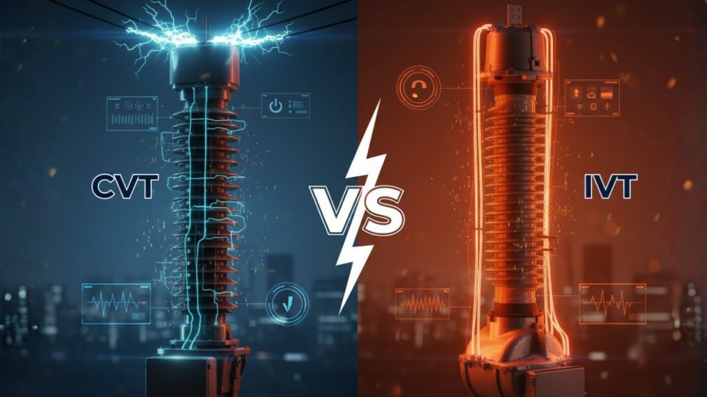
Inductive vs Capacitive Voltage Transformer in Substations – What’s the Difference?
Inductive vs Capacitive Voltage Transformer in Substations – What’s the Difference? https://www.theelectricalguy.in/wp-content/uploads/2025/11/maxresdefault-1024x576.jpg 1024 576 Gaurav Joshi https://secure.gravatar.com/avatar/f6a3006f3f7233a71d79d0e705c167ae12516870e5239627478665ae377435b3?s=96&d=mm&r=gWhen it comes to voltage transformers in substations, engineers often face one key choice, Capacitive vs Inductive Voltage Transformer. Both serve the same purpose: stepping down high voltages for measurement and protection. Yet, the way they operate and perform varies greatly.
In this guide, we’ll clearly explain how Capacitive Voltage Transformers (CVTs) differ from Inductive Voltage Transformers (IVTs). You’ll learn about their working principles, construction, weight, applications, thermal burden, and the unique advantage that makes CVTs ideal for high-voltage substations.
Table of Contents
- Working Principle of Capacitive vs Inductive Voltage Transformer
- Construction Difference Between Capacitive and Inductive Voltage Transformer
- Weight Comparison
- Cost and Feasibility at Higher Voltages
- Applications of Capacitive and Inductive Voltage Transformers
- Thermal Burden Difference
- Communication Capability in CVTs vs IVTs
- Why CVTs Dominate High-Voltage Systems
- Conclusion
Working Principle of Capacitive vs Inductive Voltage Transformer
The first and most crucial difference between Capacitive and Inductive Voltage Transformers lies in their working principle.
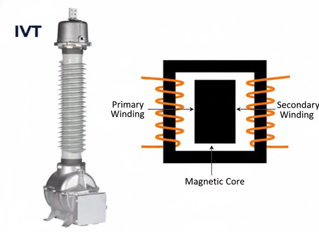
Inductive Voltage Transformer (IVT) works just like a regular power transformer. It has a primary winding, secondary winding, and a magnetic core. The voltage is stepped down through electromagnetic induction between these windings. The operation is straightforward and similar to the transformer you already know.
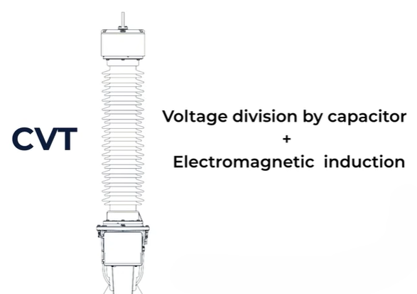
In contrast, a Capacitive Voltage Transformer (CVT) operates differently. It uses two working principles:
- Voltage division using capacitors
- Electromagnetic induction
In a CVT, capacitors are connected in series across the high-voltage line. These capacitors divide the voltage, producing a lower intermediate voltage. However, this voltage is still too high for meters or relays, often around 10 kV to 20 kV.
So, to step it down further, a small auxiliary transformer is added at the bottom of the CVT. This transformer reduces the voltage to a safer level for measuring instruments.
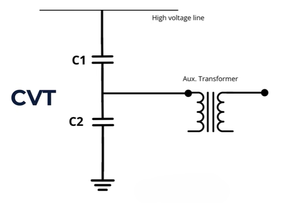
Thus, a CVT works through voltage division by capacitors and induction by a transformer. The IVT’s working principle is simple, while the CVT combines two techniques for effective voltage measurement.
Construction Difference Between Capacitive and Inductive Voltage Transformer
The construction of both transformers also differs.
An Inductive Voltage Transformer has a simple design. It includes a primary terminal, primary and secondary windings, and a magnetic core, all enclosed and filled with insulating oil. The setup is compact and has fewer components.
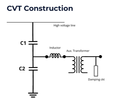
However, a Capacitive Voltage Transformer is more complex. It contains several essential parts:
- Capacitor stack for voltage division
- Auxiliary transformer to step down voltage
- Inductor to balance the phase difference caused by capacitors
- Damping circuit to prevent resonance
Since CVTs include both capacitive and inductive elements, there’s a chance of resonance. This happens when capacitive and inductive reactances cancel each other, creating a low-impedance path. This can affect output and even saturate the core.
To avoid this, a damping circuit is used. It ensures stable operation by reducing resonance risks.
Overall, CVTs have a more complicated construction than IVTs. But this complexity makes them better suited for high-voltage applications, where IVTs may become impractical.
Weight Comparison of Capacitive vs Inductive Voltage Transformer
Weight is another key factor when comparing Capacitive vs Inductive Voltage Transformer.
An Inductive Voltage Transformer contains a large magnetic core and heavy insulation. As the voltage level rises, both must be increased, making the unit bulkier. This also means it requires more insulating oil and a stronger support structure.
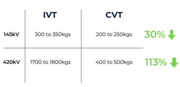
For instance, at 145 kV, an IVT typically weighs around 300 – 350 kg. In contrast, a CVT of the same rating weighs only 200 – 250 kg, about 30% lighter.
This weight difference grows at higher voltages. A 420 kV IVT may weigh 700 – 800 kg, while a 420 kV CVT only weighs 400 – 500 kg. That’s nearly half the weight.
So, CVTs are lighter, need less oil, and require less structural support. IVTs, on the other hand, become heavier and costlier as voltage ratings increase.
Cost and Feasibility at Higher Voltages
As voltage levels rise, Inductive Voltage Transformers become expensive and hard to build. The core size, insulation, and oil quantity all increase, driving up both cost and weight.
In contrast, Capacitive Voltage Transformers stay cost-effective. Their design doesn’t depend on large cores or thick insulation. Therefore, CVTs are more economical and practical at higher voltage levels.
While IVTs are still ideal for low-voltage substations, CVTs dominate at 420 kV and 800 kV systems due to their lighter, more economical design.
Applications of Capacitive and Inductive Voltage Transformers
Both CVTs and IVTs are used to step down voltage for metering and protective relays. However, their voltage range and applications vary.
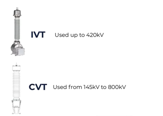
- Inductive Voltage Transformers (IVTs):
Used mainly up to 145 kV. Though some are built for 245 kV or 420 kV, such cases are rare due to design limitations. - Capacitive Voltage Transformers (CVTs):
Commonly used from 145 kV up to 800 kV. They are ideal for extra-high-voltage (EHV) and ultra-high-voltage (UHV) substations.
In short, IVTs suit lower voltages, while CVTs are preferred for high-voltage applications.
Thermal Burden in Capacitive vs Inductive Voltage Transformer
Another major difference lies in the thermal burden.
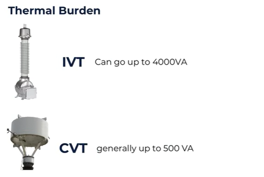
The thermal burden defines how much power you can draw from the transformer without causing overheating. It’s measured in volt-amperes (VA).
An Inductive Voltage Transformer can handle a much higher thermal burden. Depending on its design, it can deliver up to 4,000 VA without exceeding safe temperature limits.
There are also special Power Voltage Transformers that can supply even more power for voltage measurement and limited power distribution in remote areas.
On the other hand, a Capacitive Voltage Transformer usually handles only a few hundred VA, around 300 – 400 VA.
This doesn’t mean CVTs are weak. Modern digital relays and meters consume very little power. So, a few hundred VA is more than enough for their operation.
In this category, IVTs have the edge in handling larger loads. But for today’s low-power systems, CVTs perform efficiently.
Communication Capability in Capacitive vs Inductive Voltage Transformer
Now comes the biggest advantage that makes Capacitive Voltage Transformers dominate high-voltage substations, their ability to support communication systems.
High-voltage transmission lines carry not just power, but also communication signals. These signals operate at very high frequencies up to 500 kHz, while power operates at 50 – 60 Hz.
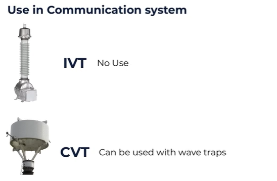
Inductive Voltage Transformers cannot handle these high-frequency signals. They only serve power frequency measurement and protection roles.
However, Capacitive Voltage Transformers can perform both roles. When combined with wave traps, CVTs can transmit Power Line Carrier Communication (PLCC) signals.
This means the same transmission line can carry both power and communication data. The CVT acts as a coupling capacitor, allowing communication signals to pass while blocking the 50 Hz power frequency.
In contrast, when using an IVT, a separate coupling capacitor is required for communication, which adds extra cost and equipment.
Because CVTs already integrate this function, they save both space and money, making them ideal for modern substations.
This ability to enable PLCC is the main reason why CVTs dominate the high-voltage and extra-high-voltage market.
Why CVTs Dominate High-Voltage Applications
When comparing Capacitive vs Inductive Voltage Transformer, several points make CVTs the better choice for high-voltage use:
- Lightweight and compact design reduces structure costs.
- Lower insulation and oil requirements make them more economical.
- Integrated communication support (PLCC) eliminates extra coupling devices.
- Efficient voltage stepping suitable up to 800 kV systems.
IVTs, though simpler, become heavy, expensive, and impractical at high voltages. They are still valuable for low- and medium-voltage systems, where their simplicity and high thermal burden are advantageous.
Summary Table: Capacitive vs Inductive Voltage Transformer
| Feature | Inductive Voltage Transformer (IVT) | Capacitive Voltage Transformer (CVT) |
| Working Principle | Electromagnetic induction only | Voltage division by capacitors + induction |
| Construction | Simple | Complex (with capacitors, inductors, damping circuit) |
| Weight | Heavy, more oil | Lighter, less oil |
| Voltage Range | Up to 145 kV (rarely 420 kV) | From 145 kV to 800 kV |
| Thermal Burden | High (up to 4,000 VA) | Moderate (300–400 VA) |
| Communication (PLCC) | Not supported | Supported (acts as coupling capacitor) |
| Cost at High Voltage | Expensive | Cost-effective |
| Applications | Low- and medium-voltage substations | High-voltage and EHV substations |
Conclusion
Both Capacitive and Inductive Voltage Transformers are vital components in power systems. While IVTs are simple, strong, and efficient for low voltages, CVTs are lighter, more cost-effective, and ideal for high-voltage systems.
The ability of CVTs to support power line carrier communication (PLCC) makes them the preferred choice in modern substations.
If you want a clearer visual understanding of how these two transformers differ, watch the full video titled “Capacitive VS Inductive Voltage Transformer | What’s the Difference?” on YouTube for step-by-step explanations and diagrams.
