
What Are Accuracy Classes of CT? Complete Guide to Metering and Protection
What Are Accuracy Classes of CT? Complete Guide to Metering and Protection https://www.theelectricalguy.in/wp-content/uploads/2026/02/maxresdefault-2-1-1024x576.jpg 1024 576 Gaurav Joshi https://secure.gravatar.com/avatar/f6a3006f3f7233a71d79d0e705c167ae12516870e5239627478665ae377435b3?s=96&d=mm&r=gAccuracy in general means correctness. In current transformers, it refers to how closely the secondary current matches the scaled primary current. If the output is accurate, the CT performs well. If errors appear, measurement and protection suffer.
A CT does not only measure current. It also provides input to protection systems. Therefore, inaccurate output can cause serious problems. Wrong readings affect billing. Wrong relay signals can delay fault clearing. Because of this, accuracy remains a core performance parameter in CT design and selection.
Table of Contents
- Why Accuracy Is Divided into Two Categories
- Separate Cores for Metering and Protection
- Behavior of Protection Cores During Faults
- Behavior of Metering Cores During Overload
- Errors in Current Transformers
- IEC Standards for CT Accuracy Classes
- Metering Accuracy Classes of CT
- Performance Requirements for Metering Classes
- Naming Logic of Metering Accuracy Classes
- Protection Accuracy Classes of CT
- Characteristics of 5P and 10P Classes
- Composite Error in Protection CTs
- Special Protection Classes: PX and PS
- Testing of Accuracy Classes
- Relationship Between Burden and Accuracy
- Practical Importance of Accuracy Classes of CT
- Common Application Examples
- Conclusion
Why Accuracy Is Divided into Two Categories
Current transformers serve two main purposes. First, they supply current to meters. Second, they supply current to protection relays. These two functions require different performance behavior.
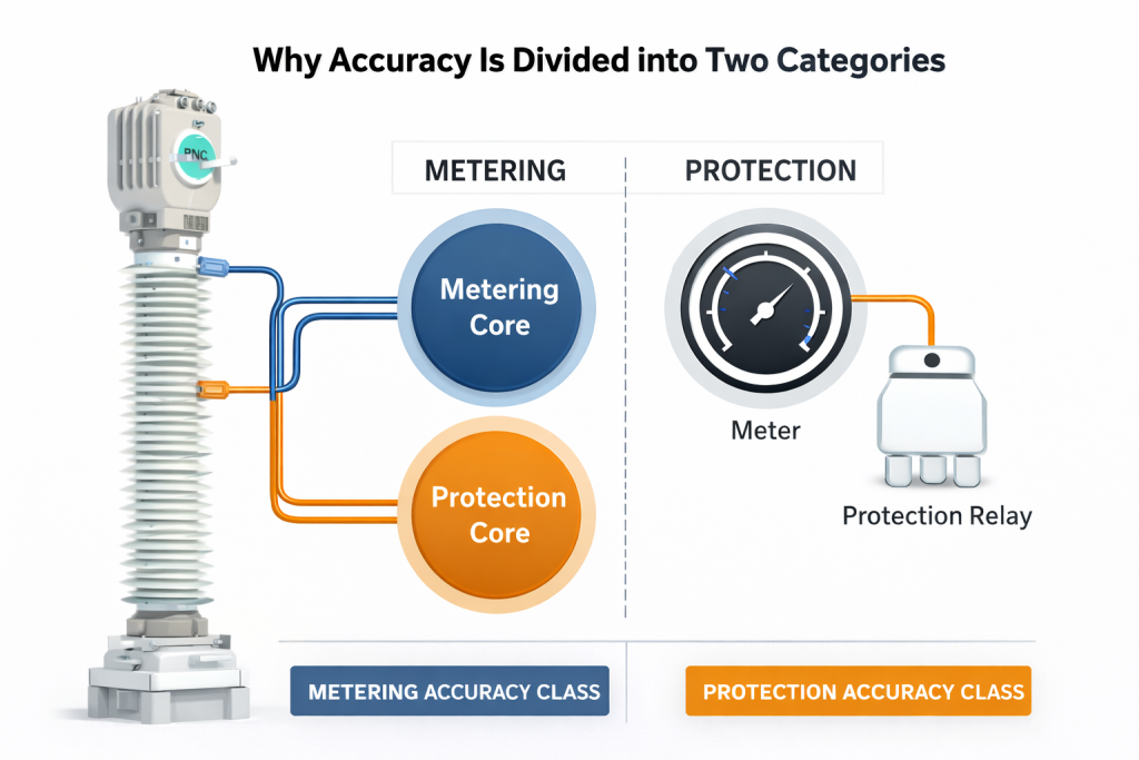
Meters need precise values under normal conditions. Relays need reliable values during faults. One CT core cannot satisfy both needs efficiently. For this reason, manufacturers provide separate cores. Each core is designed with different characteristics. These characteristics define the Accuracy Classes of CT.
Separate Cores for Metering and Protection
A single CT often contains multiple cores. Each core serves a specific purpose. One core connects to meters. Others connect to protection relays.
For example, one CT may have three cores. One core supports measurement. Two cores support distance and differential protection. Each core works independently.
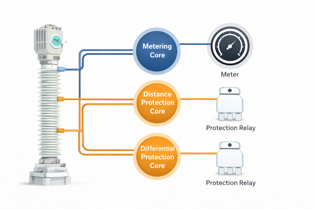
What differentiates these cores is accuracy design. Metering cores focus on precision. Protection cores focus on reliability during faults. This separation ensures safe and efficient operation.
Behavior of Protection Cores During Faults
Protection cores must work during abnormal conditions. During faults, primary current rises sharply. In some cases, it reaches many times the rated value.
Under such conditions, the protection core must still produce output. It should not saturate. If saturation occurs, the relay will not receive proper input. As a result, fault clearance may fail.
Therefore, protection cores are designed to remain stable at high currents. Their magnetic properties allow them to handle overloads. Accuracy under fault conditions is more important than precision.
Behavior of Metering Cores During Overload
Metering cores behave differently. Meters are sensitive devices. They cannot withstand high currents. If a metering core produces high output during faults, the connected meter may burn. This creates safety and financial risks.
Therefore, metering cores are designed to saturate early. When current becomes excessive, output reduces. This protects meters from damage. This controlled saturation is intentional. It is part of metering accuracy design.
Errors in Current Transformers
Several types of errors affect CT performance. These errors determine the accuracy class.
One major error is ratio error. It represents the difference between actual transformation ratio and rated ratio. Another error is phase displacement. It shows the angle difference between primary and secondary currents.
Composite error also appears in protection CTs. It combines magnitude and phase errors under fault conditions. Standards specify limits for these errors. A CT must remain within limits to qualify for a specific class.
IEC Standards for CT Accuracy Classes
International standards guide CT performance. The IEC sets widely accepted rules. For instrument transformers, IEC defines accuracy classes and limits.
Each class specifies allowable errors. These limits depend on current level and burden. Only CTs that meet these requirements receive certification. IEC standards ensure uniform quality worldwide.
Metering Accuracy Classes of CT
Metering accuracy focuses on precision. It ensures correct measurement during normal operation. IEC defines several metering classes. These include 0.1, 0.2, 0.2S, 0.5, 0.5S, 1, 3, and 5.
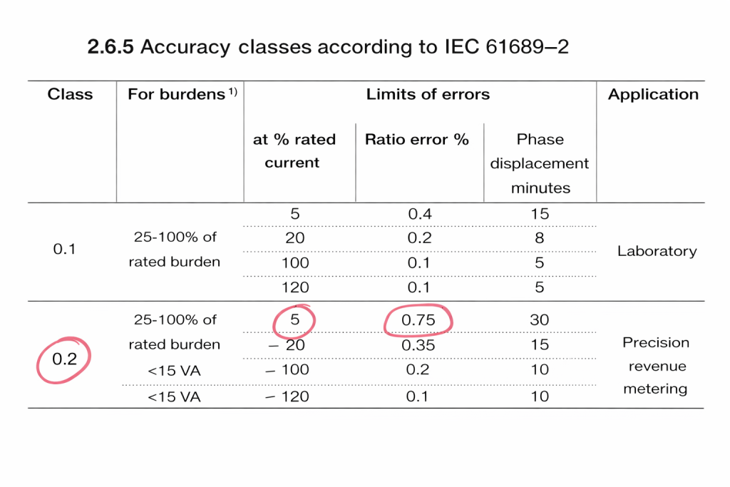
Each class represents maximum permissible ratio error at rated current. Lower numbers indicate better accuracy. For example, class 0.2 allows only 0.2% error at rated current. This makes it highly precise.
Performance Requirements for Metering Classes
Metering CTs must maintain accuracy over a range of currents. IEC specifies test points at 5%, 20%, 100%, and 120% rated current. At each point, ratio and phase errors must remain within limits. If the CT fails at any point, it loses its class.
Phase displacement also matters. It affects power and energy measurement. Therefore, both magnitude and phase errors are controlled. Among all metering classes, 0.2S is the most accurate. Utilities often use it for revenue metering.
Naming Logic of Metering Accuracy Classes
The naming of metering classes follows a simple rule. The class number equals the maximum ratio error at rated current. For example, class 1 allows 1% error. Class 0.5 allows 0.5% error. Class 0.2 allows 0.2% error.
This naming system makes selection easy. Engineers can quickly judge performance from the class number.
Protection Accuracy Classes of CT
Protection accuracy differs from metering accuracy. CTs do not need extreme precision. Instead, they must perform under fault conditions. IEC defines protection classes such as 5P, 10P, PX, and PS.
These classes focus on behavior at high currents. They ensure that CTs supply usable signals to relays during faults. Reliability takes priority over precision.
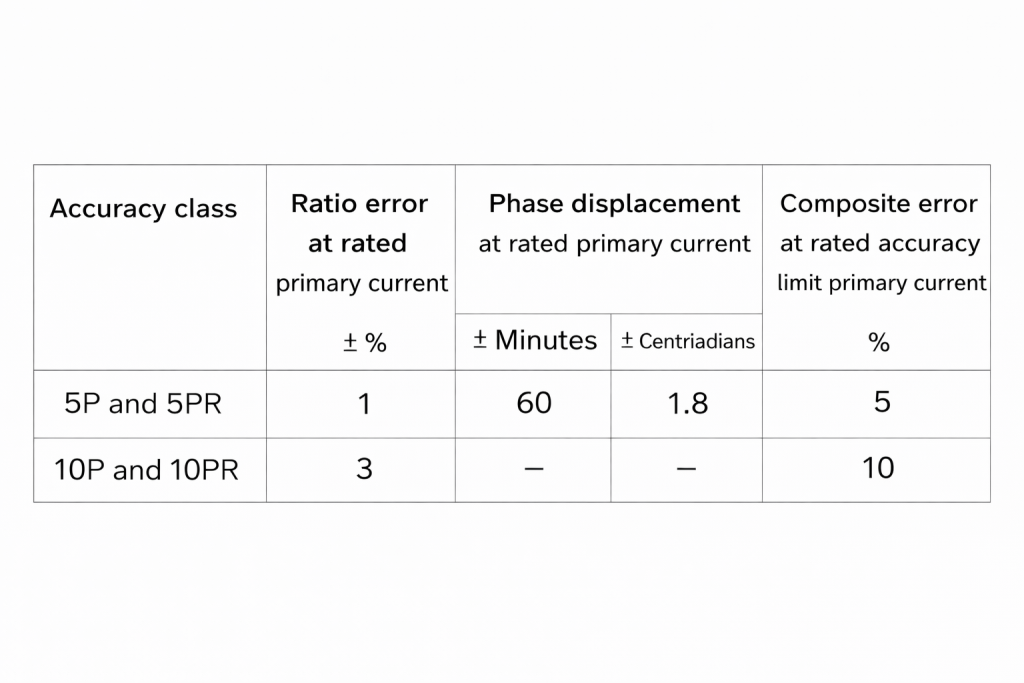
Characteristics of 5P and 10P Classes
The most common protection classes are 5P and 10P. In class 5P, ratio error must remain within 1% at rated current. Composite error must stay below 5% at specified fault current.
In class 10P, composite error limit is 10%. This allows higher error but still ensures relay operation. Compared to metering classes, these values are much higher. This shows that protection focuses on stability, not fine accuracy.
Composite Error in Protection CTs
Composite error represents total deviation under fault conditions. It includes both ratio and phase effects. During faults, CTs experience high flux. This creates distortion. Composite error measures how badly output deviates.
IEC specifies limits for composite error in 5P and 10P classes. These limits ensure that relays receive sufficient current. Without composite error control, protection would fail.
Special Protection Classes: PX and PS
PX and PS classes serve advanced protection schemes. They are used in differential and distance protection. These classes do not follow standard error tables. Instead, they require specific knee point voltage, resistance, and excitation current values.
Engineers design PX and PS CTs for customized applications. They offer high stability and low saturation. Such CTs are common in critical substations.
Testing of Accuracy Classes
Accuracy classes are not assumed. Manufacturers must prove them through testing. CTs undergo laboratory tests. Engineers apply different currents and burdens. They measure ratio error and phase displacement. For protection CTs, fault simulations are performed. Composite error is evaluated. Only after passing all tests does a CT receive its accuracy rating.
Relationship Between Burden and Accuracy
Accuracy depends strongly on burden. IEC guarantees accuracy only within a specific burden range. Accuracy remains valid between 25% and 100% of rated burden. Outside this range, errors may increase.
If burden exceeds the rating, CT saturation occurs. If burden is too low, magnetizing current increases. Both conditions degrade accuracy. Therefore, proper burden selection is essential.
Practical Importance of Accuracy Classes of CT
Correct accuracy selection ensures safe system operation. Metering accuracy protects revenue. Protection accuracy ensures fast fault clearance. Wrong class selection creates serious risks. Poor metering accuracy leads to billing disputes. Weak protection accuracy causes delayed tripping. Understanding Accuracy Classes of CT helps engineers design reliable systems. It also improves interview performance and field competence.
Common Application Examples
Utilities use 0.2S class CTs for billing meters. Industrial plants often use 0.5 class for internal monitoring. Distance and differential relays usually require 5P or PX class CTs. Backup protection may use 10P class. Each application demands specific accuracy behavior. Proper matching avoids failures.
Conclusion
Accuracy Classes of CT form the foundation of reliable current measurement and protection. They define how CTs behave under normal and fault conditions. Metering accuracy ensures correct billing. Protection accuracy ensures system safety. Both depend on proper class selection and burden management.
Engineers must understand standards, error limits, and core behavior. This knowledge improves design quality and operational reliability. For better practical understanding, watch the referenced video. It explains CT accuracy with clear examples and visual demonstrations.
