
What Do Accuracy Classes 0.1, 0.2, 0.2S, 5P Mean
What Do Accuracy Classes 0.1, 0.2, 0.2S, 5P Mean https://www.theelectricalguy.in/wp-content/uploads/2025/10/maxresdefault-1-1024x576.jpg 1024 576 Gaurav Joshi https://secure.gravatar.com/avatar/f6a3006f3f7233a71d79d0e705c167ae12516870e5239627478665ae377435b3?s=96&d=mm&r=gInstrument transformers play a vital role in power systems. We use current transformers (CTs) and voltage transformers (VTs) to step down current and voltage from the grid. The reason is simple. The devices connected to them, meters and relays, cannot handle large currents or voltages directly.
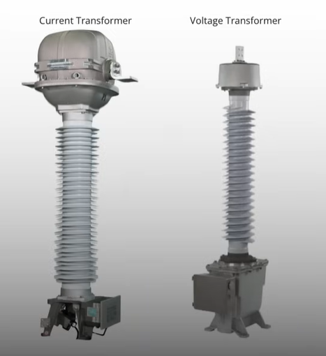
For example, a relay or meter cannot take 2000A of current. They need small input values such as 1A or 5A. So, a current transformer reduces the current to this safe level.
The same logic applies to voltage transformers, which step down voltage to levels that meters and relays can process.
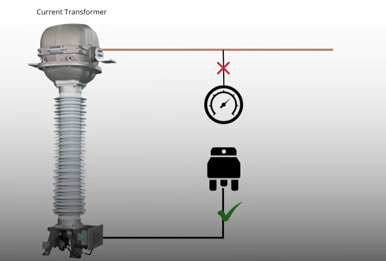
The output from these transformers then goes to relays for protection and to meters for measurement. Though both protection and measurement use the same transformer, their needs are very different.
Table of Content
- Protection and Measurement Have Different Purposes
- Why Instrument Transformers Have Multiple Cores
- Understanding Ratio Error
- IEC Standards for Accuracy Classes
- Accuracy Classes for Voltage Transformers
- Accuracy Classes for Current Transformers
- Comparing Metering and Protection Classes
- Understanding “P” and “S” in Accuracy Classes
- Why You Should Choose the Right Accuracy Class
- Example Scenario
- Phase Displacement and Its Role
- Ratio Error vs. Application
- Conclusion
Protection and Measurement Have Different Purposes
Protection systems need to work even during faults. When a fault occurs, very high current flows through the system. The protection CT must still provide output to the relay so that it can detect the fault and act. If it fails to deliver accurate signals during a fault, the relay may not trigger, leading to dangerous situations.
On the other hand, measurement systems focus on accuracy. A small error in a measuring CT or VT affects billing and energy calculations. Therefore, metering requires high precision. But when a fault occurs, the CT used for measurement should not deliver large outputs. This protects the meter from damage.
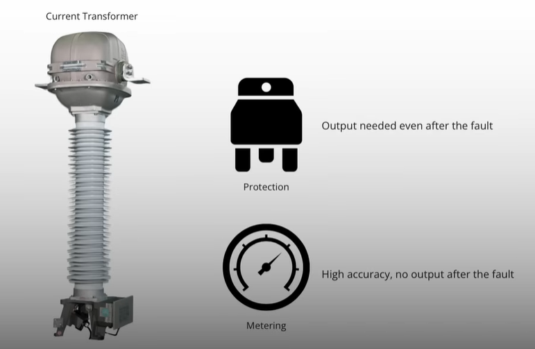
Thus, protection and measurement have opposite requirements. One needs accuracy under normal conditions, while the other needs reliability under fault conditions.
Why Instrument Transformers Have Multiple Cores
Because of these different needs, instrument transformers have separate cores, one for protection and another for metering. Each core has its own design and accuracy characteristics.
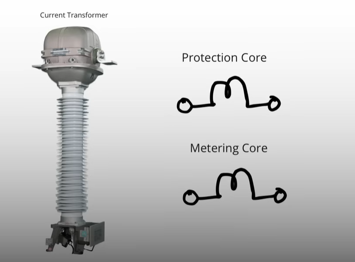
If we use the same core for both purposes, it will not perform well. For example, a metering core might saturate during a fault, while a protection core might have high errors under normal load.
Hence, manufacturers design and test each core for a specific function. To classify these characteristics, international standards like IEC and IEEE define accuracy classes for instrument transformers.
Understanding Ratio Error
Before going deeper into accuracy classes, let’s understand one key parameter, ratio error.
In simple terms, ratio error is the difference between the actual ratio and the ideal ratio of a transformer. The higher the ratio error, the lower the accuracy.
For example, if a voltage transformer should step down 11kV to 110V, but in reality, it outputs 112V, then there’s a ratio error. In metering applications, even a small error can cause billing inaccuracies.
That’s why metering cores need very low ratio errors. However, in protection, such small errors are acceptable because accuracy is less important than reliable fault detection.
IEC Standards for Accuracy Classes
The IEC 61869 series (for instrument transformer above 1000V) defines the accuracy classes for both voltage and current transformers. These classes tell us how much error a transformer can have under specific conditions.
Let’s first look at voltage transformers (VTs).
Accuracy Classes for Voltage Transformers
The IEC defines separate accuracy classes for metering and protection in VTs.
Metering Accuracy Classes: 0.1, 0.2, 0.5, 1, and 3
For metering cores, the IEC defines accuracy classes 0.1, 0.2, 0.5, 1, and 3.
These numbers represent the percentage of ratio error allowed at rated voltage and rated burden. For instance, a 0.2 class VT can have a maximum ratio error of 0.2%.
So, a class 0.1 transformer is more accurate than class 0.5. The smaller the number, the higher the accuracy.
Each class also has a defined phase displacement, which is the angle difference between the primary and secondary voltages. IEC 61869-3 provides a table showing these limits.
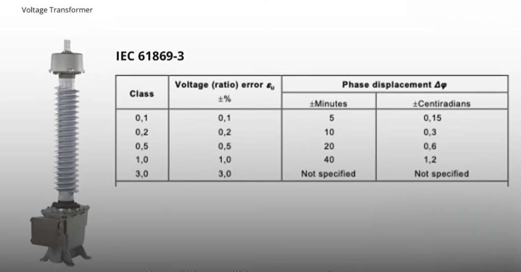
If a VT’s ratio error is within 0.2% and its phase displacement meets IEC limits, it qualifies as a 0.2 class transformer.
This accuracy is important in applications where precise energy measurement is needed, such as billing and monitoring.
Protection Accuracy Classes: 3P and 6P
For protection cores, IEC defines 3P and 6P accuracy classes.
Here, “P” stands for “Protection,” and the number indicates the percentage of ratio error allowed.
For example, in class 3P, the allowed ratio error is 3%. In class 6P, it’s 6%. These are much higher than metering classes like 0.2.
This means protection cores can tolerate higher errors because their main job is to ensure fault detection, not precision measurement.
The IEC table also defines the phase displacement for these classes.
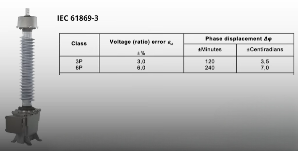
If you compare, metering classes like 0.1 or 0.2 are far more accurate than protection classes like 3P. Therefore, using a protection core for metering will cause significant measurement errors. Likewise, using a metering core for protection may lead to failures during faults.
Accuracy Classes for Current Transformers
The IEC 61869-2 standard defines accuracy classes for current transformers (CTs).
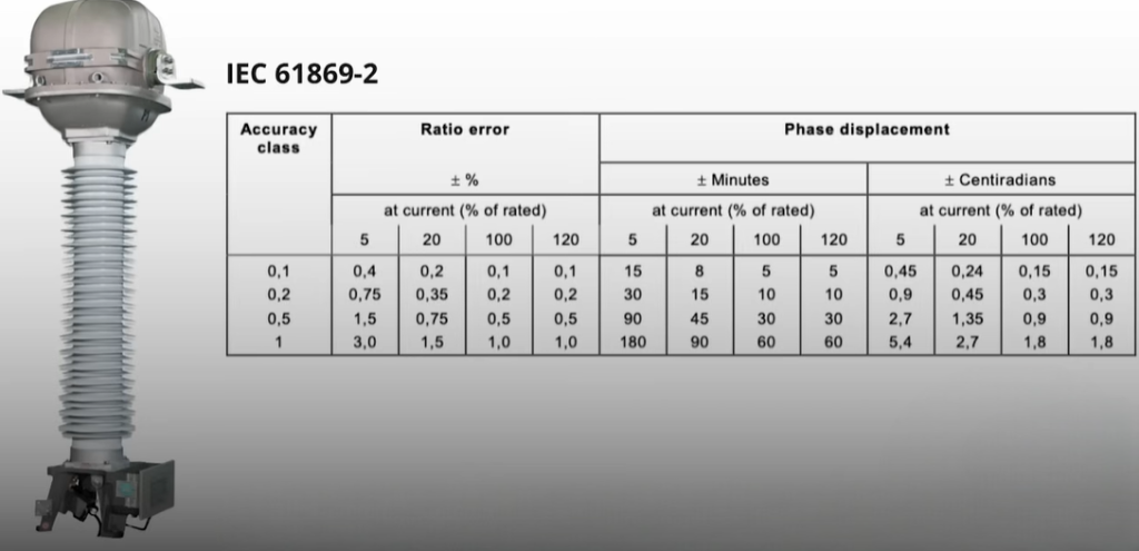
Just like voltage transformers, CTs also have separate metering and protection classes. The idea remains the same, accuracy for metering, reliability for protection.
Metering Classes: 0.1, 0.2, 0.2S, 0.5, 1, and 3
For metering CTs, accuracy classes such as 0.1, 0.2, 0.2S, 0.5, 1, and 3 are defined.
Here, the accuracy class indicates the percentage of ratio error allowed at rated primary current. The test points are usually at 5%, 20%, 100%, and 120% of the rated primary current.
For example, a 0.2 class CT has a ratio error within 0.2% when tested at these currents.
You might notice an additional class, 0.2S. The letter “S” stands for “Special.” This class has tighter error limits and is used in applications that require even higher accuracy, like energy billing and revenue metering.
Thus, the classes 0.1 and 0.2S ensure extremely precise measurements.
Protection Classes: 5P and 10P
For protection CTs, the IEC defines 5P and 10P accuracy classes.
Again, the number indicates the maximum ratio error allowed. For a 5P class CT, the error limit is 5%. For 10P, it’s 10%.
These transformers are designed to stay accurate even during fault conditions. During a fault, the current may rise many times higher than the rated current. The CT should still produce an output so the relay can detect the fault correctly.
In contrast, a metering CT would likely saturate during such high currents, cutting off the output to protect the meter. That’s why each core must serve its specific purpose.
IEC also defines special classes like PS or PX, but those are used for very specific relay protection schemes and are not covered here.
Comparing Metering and Protection Classes
Now that we’ve seen both, let’s compare metering and protection accuracy classes.
| Purpose | Example Classes | Ratio Error | Accuracy Focus | Response During Fault |
| Metering | 0.1, 0.2, 0.2S, 0.5 | Very low (0.1–0.5%) | High precision for billing | Should not output during fault |
| Protection | 3P, 5P, 10P | High (3–10%) | Reliable fault detection | Must output during fault |
As the table shows, metering transformers prioritize accuracy under normal conditions. Protection transformers prioritize reliability during abnormal conditions.
That’s why you should never mix them. Using a protection CT for metering can cause large billing errors. Using a metering CT for protection can cause a relay to miss a fault.
Understanding “P” and “S” in Accuracy Classes
Many people wonder what the letters “P” and “S” mean in classes like 5P and 0.2S.
The “P” in 5P or 10P stands for Protection. These CTs or VTs ensure the protection relay gets the correct current or voltage signal during faults.
The “S” in 0.2S stands for Special. It refers to special metering accuracy. These CTs or VTs maintain precise accuracy across a wider current range compared to standard classes.
For example, a 0.2S CT maintains 0.2% accuracy even at very low currents, while a regular 0.2 class may not.
Why You Should Choose the Right Accuracy Class
Choosing the correct accuracy class depends on your purpose.
If your goal is measurement or billing, use CTs or VTs with metering classes like 0.1, 0.2, or 0.2S. These ensure precise readings and accurate billing.
If your goal is protection, use CTs or VTs with protection classes like 5P or 10P. These will operate reliably even during high fault currents.
Using the wrong class can cause serious issues, either inaccurate energy data or failure of protective relays.
Example Scenario
Let’s take an example of a voltage transformer used in a substation.
One core of the VT connects to a relay for protection. The other connects to a meter for measurement.
If you use a 0.2 class core for metering, you’ll get highly accurate readings. But using the same 0.2 class core for protection could be risky because it might saturate during faults.
Instead, for protection, you should use a 3P class core. It can handle high fault voltages without losing output.
This is why a single VT often comes with two cores, one for protection and one for metering.
Phase Displacement and Its Role
Another key factor in accuracy classes is phase displacement.
It’s the angular difference between the primary and secondary voltage or current vectors. Even small phase errors can affect power and energy measurement.
That’s why IEC standards specify the maximum allowed phase displacement for each class. For example, a 0.2 class VT must keep the phase displacement within a few minutes of a degree, while a 3P class allows much more.
Phase accuracy is critical for metering but less so for protection.
Ratio Error vs. Application
To summarize, the ratio error defines how much the actual transformation differs from the ideal ratio.
- Low ratio error (0.1–0.2%) → Needed for metering
- High ratio error (3–10%) → Acceptable for protection
Protection transformers must remain linear during faults, even if accuracy suffers. Metering transformers must remain accurate during normal conditions, even if they stop working under faults.
Conclusion
Accuracy classes such as 0.1, 0.2, 0.2S, and 5P define how precise or robust an instrument transformer is. Each serves a specific purpose, metering or protection.
A 0.1 or 0.2S class ensures accurate billing data. A 5P or 10P class ensures your system remains protected during faults.
Remember, never interchange the two. Always use the correct core for the right purpose.
If you still find this topic tricky, watch the detailed video linked in the description. It explains the concepts visually and will make everything much clearer.
