
How Engineers Test Substation Grounding
How Engineers Test Substation Grounding https://www.theelectricalguy.in/wp-content/uploads/2025/12/maxresdefault-3-1024x576.jpg 1024 576 Gaurav Joshi https://secure.gravatar.com/avatar/f6a3006f3f7233a71d79d0e705c167ae12516870e5239627478665ae377435b3?s=96&d=mm&r=gTesting a grounding system is not easy. You cannot see the grid. You also cannot touch it. It stays under the soil. Yet it protects every person and every device inside a substation. Because of that, engineers must test it well. In this guide, you will learn how engineers test substation grounding using simple steps.
Grounding tests follow standards. Most engineers use IEEE 81. This standard guides how to measure earth resistivity, ground impedance, and surface voltage. It also helps define safe limits. Following it ensures accurate and safe results.
Before we move to the tests, we must recall why grounding matters. This helps us understand why each test exists.
Table of Contents
- Purpose of Substation Grounding
- Fall-of-Potential Test for How Engineers Test Substation Grounding
- Ground Grid Integrity Test for How Engineers Test Substation Grounding
- Soil Resistivity Test for How Engineers Test Substation Grounding
- Touch and Step Voltage Test for How Engineers Test Substation Grounding
- Why All Methods Use the Same Idea
- Conclusion
Purpose of Substation Grounding
The main purpose of a grounding system is safety. It must carry fault current straight to the soil. It must also carry lightning current deep into the ground. The current should not enter a human body. It should not flow into other equipment.
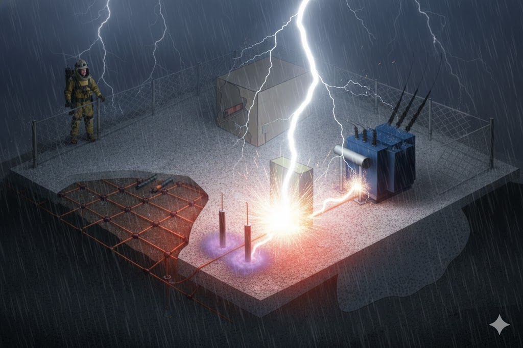
Another purpose is to keep the ground potential rise low. High GPR creates step and touch voltage. These voltages are dangerous. They can harm workers. Standards define the safe levels. The grounding system must stay below those limits.
Every test checks these two points. First, the system should have low impedance. A low value allows fault current to pass with ease. Second, the grid must stay healthy. Each joint must stay connected. No part should break. No part should corrode. Both goals support a safe substation.
Engineers use four main methods to test grounding:
- Fall-of-Potential Test
- Ground Grid Integrity Test
- Soil Resistivity Test
- Touch and Step Voltage Test
The first two tests are the most common. The last two are used for new substations. Now let us move into the details.
Fall-of-Potential Test for How Engineers Test Substation Grounding
The Fall-of-Potential Test checks the impedance of the ground grid. It is simple. The method works well in most cases. Many engineers around the world rely on it. When impedance stays low, the system can carry fault current. When impedance rises, the system may fail.
Many people also call this resistance. The grid uses copper conductors. Copper offers resistance. So, resistance and impedance mean almost the same thing here.
How the Test Works
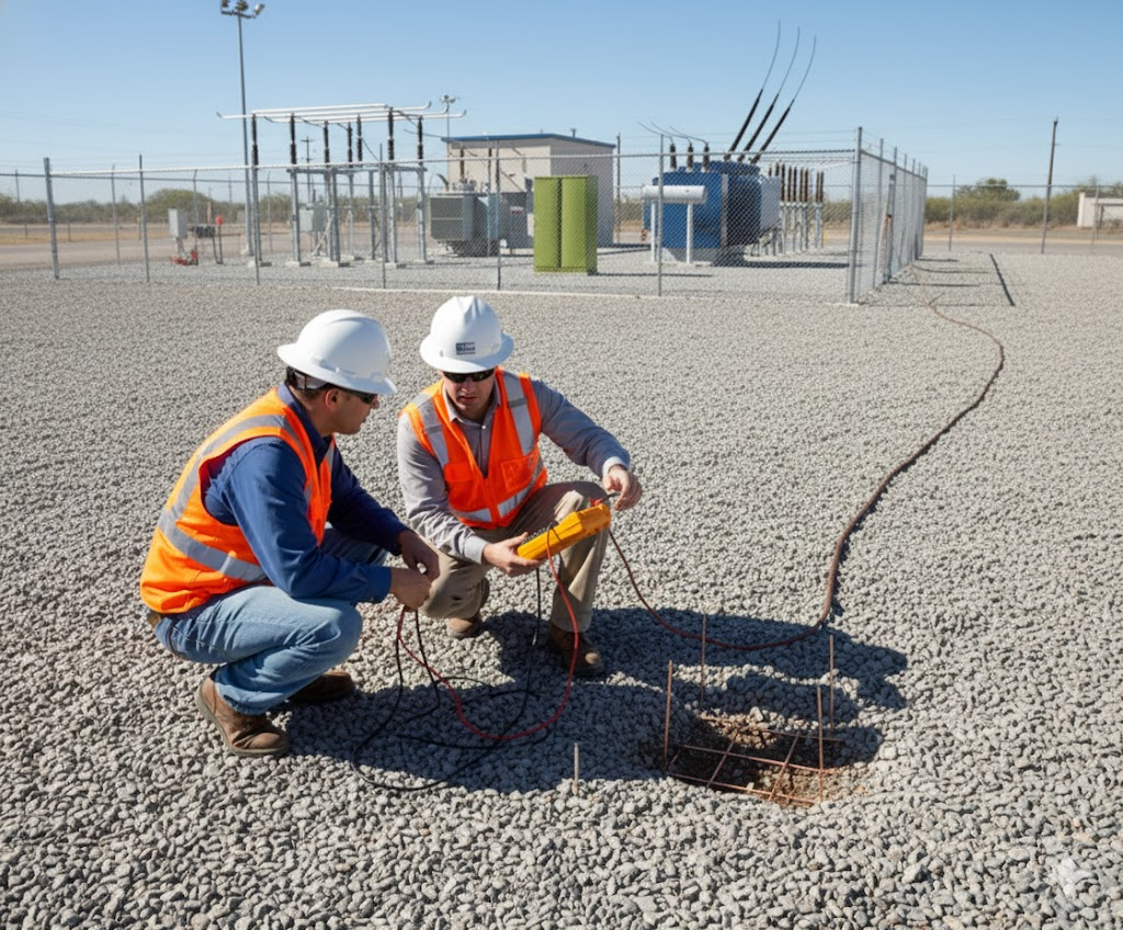
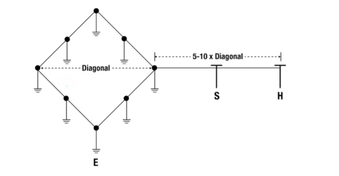
Engineers use a ground impedance tester. This tester sends a small current into the soil. For that test, they use two electrodes. One connects to the substation grid. The other goes into the soil at a set distance.
Before the test starts, engineers isolate the substation grid. They remove all links to other grounding systems. This prevents false readings. For example, they disconnect the link between the substation and a nearby tower. This gives a clean and accurate measurement.
The second electrode must stay far from the grid. The distance must follow standards. It should be five to ten times the diagonal length of the grid. For example, if the grid diagonal is 10 feet, the test electrode must stay 50 to 100 feet away.
The tester sends current into the ground electrode. The current flows through the soil. Then it enters the grid. It then returns to the tester. That completes the path.
Measuring Voltage Drop
Engineers cannot read resistance directly. They must measure voltage drop first. They know the current they supply. This helps them calculate resistance using simple math.

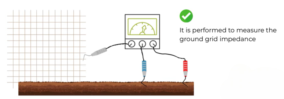
To measure the voltage drop, engineers add a third electrode. This is the potential electrode. It stays close to the grid during the first reading.
They place it near the grid, take a reading, then move it a bit farther. They continue this step many times. Each time they record the voltage drop. The rise in drop shows the rise in resistance. These values show how the potential falls with distance. This is why the method is called the Fall-of-Potential Test.
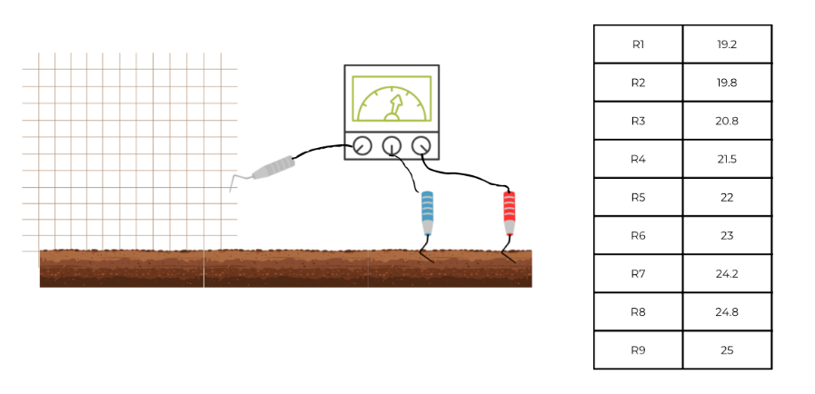
They take around nine to ten readings. These readings help build a clear graph. The middle readings usually stay stable. Engineers take an average of those. That average shows the grid resistance.
Interpreting the Result
If the resistance stays below the standard limit, then the grid is healthy. The system can carry fault current well. If the value stays high, then there may be a problem. The grid may have a break. A joint may be loose. Some parts may have corroded. Engineers then inspect the area further.
This method remains one of the most trusted tests worldwide. It offers clear results. It also matches field conditions well.
Ground Grid Integrity Test for How Engineers Test Substation Grounding
The next method checks the health of the grid. Engineers must ensure the conductors stay connected. They must also ensure no path is broken. This test finds breaks, corrosion, and weak joints.
This test works like a continuity check. Many people check a wire with a multimeter. If the meter beeps, the wire has continuity. If it stays silent, the wire has a break. That idea stays the same here. However, this test uses much higher current because the grid is huge.
How the Test Works
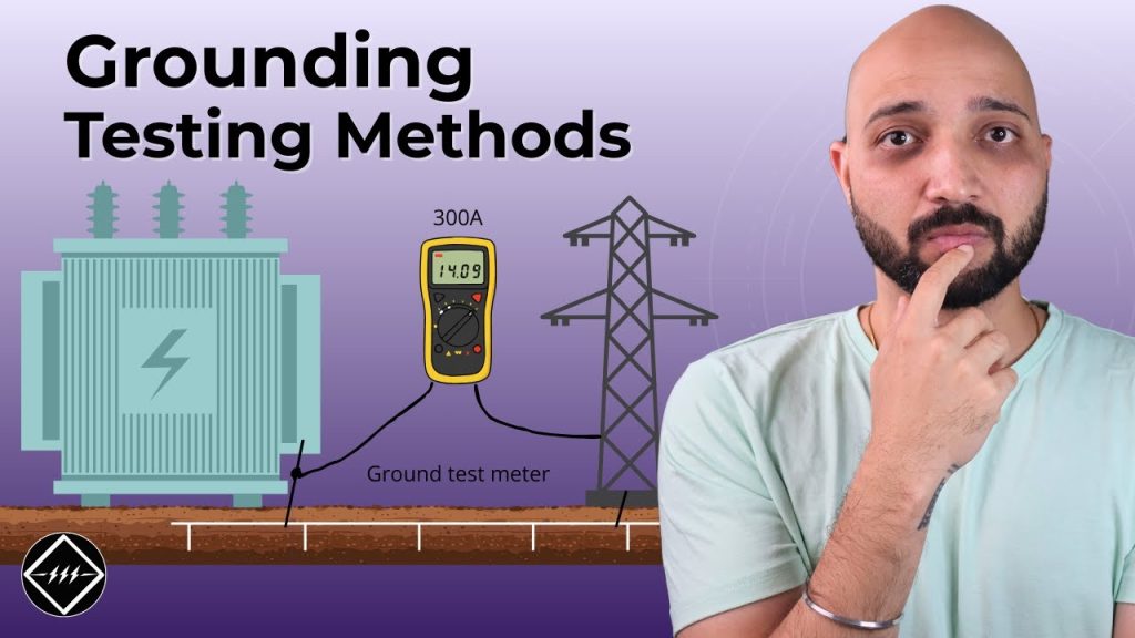
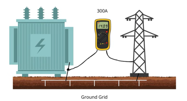
Engineers connect the test meter to two points. One point may be the transformer earthing. Another may be the gantry steel or a tower. They pass high current between them. This current can reach 300 amps AC or DC.
When current flows, voltage drop appears across the path. The meter reads this drop. Using this value, engineers calculate resistance.
If the resistance is low, the grid path is healthy. The conductors have good contact. The path is continuous. If the resistance is high, then something is wrong. A joint may be damaged. Corrosion may have formed. A connection may have become loose. Engineers can then inspect the exact zone.
They repeat this test across many pairs of points. This ensures full coverage of the grid. This test works on old substations and new ones. It remains one of the simplest ways to find hidden faults.
Soil Resistivity Test for How Engineers Test Substation Grounding
The next test is the Soil Resistivity Test. Engineers use it before building a substation. It helps them decide what grounding design they should adopt. Soil resistivity changes across locations. Soil conditions vary widely across locations. In some areas, the soil holds moisture. Other sites may have dry, compact soil. Layers can also shift with depth, which changes how the ground conducts electricity. All these factors affect grounding.
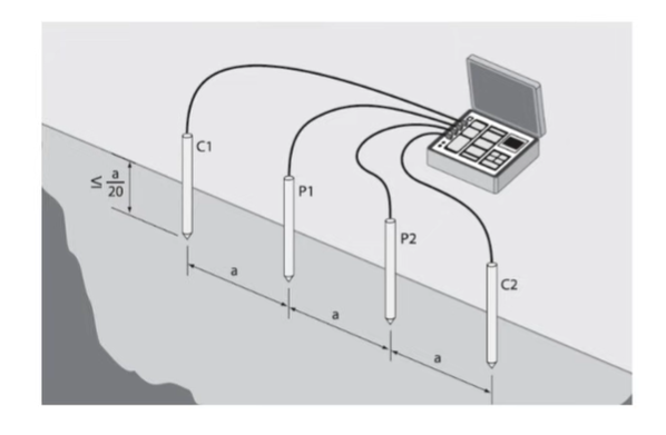
This test also uses voltage drop. Engineers apply current between electrodes. Then they measure the resistivity of the soil. Using this value, they choose the grid layout. They also decide the depth and size of conductors. Because of that, this test is done only once. It is done before any construction begins.
The transcript does not go deep here. So, we will keep it simple. The main point is that this test guides the design. It does not test the built system. It supports planning for new substations.
Touch and Step Voltage Test for How Engineers Test Substation Grounding
The final method checks touch and step voltages. These voltages appear when someone stands near a metal part. They also appear when someone touches a metal part during a fault. The potential difference between two points can harm a person. Because of that, engineers must measure it.
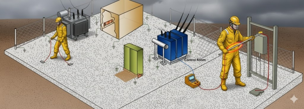
This test also uses voltage drop. Engineers place a metal plate on the soil to mimic a foot. They then place a voltage probe. The tester creates current flow. The meter shows the voltage drop between those points.
If the drop stays below the safe limit, the system passes. If not, the design must change. Engineers may need more conductors. They may also need surface layers. The transcript says this test appears in new substations. It is not very common in older sites. However, it plays an important role during commissioning.
Why do all Methods Use the Same Idea
All grounding tests follow one core principle. Engineers create current flow. Then they measure voltage drop. Then they calculate resistance. This simple idea supports each method.
Fall-of-Potential checks grid impedance.
Ground Grid Integrity checks continuity.
Soil Resistivity checks the nature of the ground.
Touch and Step checks surface voltage under stress.
Each test supports a part of the overall safety goal.
Conclusion
Testing substation grounding is essential. Each method checks one part of the system. Together they build a complete picture. You learned how engineers test substation grounding using simple steps. These methods ensure the grid can carry fault current. They also ensure workers stay safe. For a clearer understanding, you can watch the original video.
