
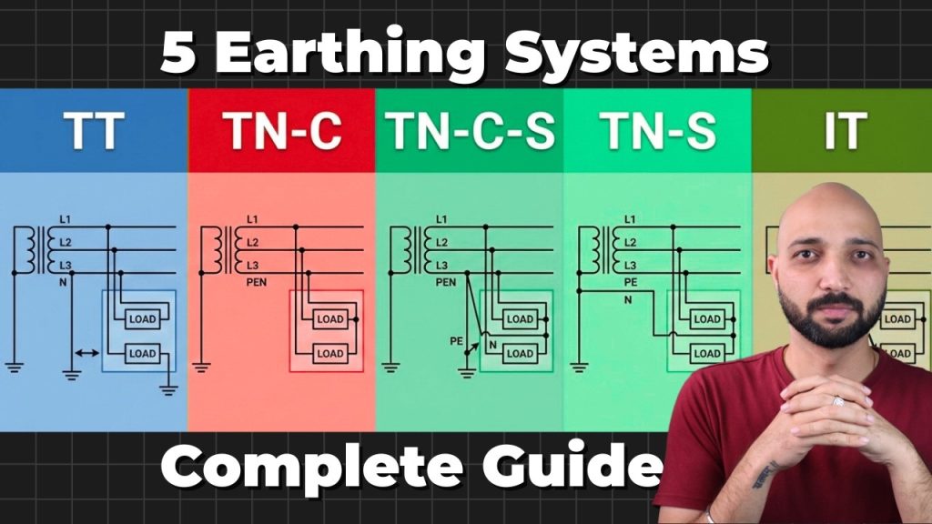
Types of Earthing Systems
Types of Earthing Systems https://www.theelectricalguy.in/wp-content/uploads/2026/03/maxresdefault-1024x576.jpg 1024 576 Gaurav Joshi https://secure.gravatar.com/avatar/f6a3006f3f7233a71d79d0e705c167ae12516870e5239627478665ae377435b3?s=96&d=mm&r=gElectrical safety depends heavily on proper grounding. Two buildings may operate at the same voltage level. Yet their safety level can differ greatly. The difference often comes from the types of earthing systems used in the installation. Many engineers work with earthing systems every day. However, many still do not fully understand how these systems differ. A poorly designed earthing arrangement can turn a simple insulation fault into a serious shock hazard.
You may install the best cables and the best circuit breakers. You may even install the best electrical panel. Yet a weak earthing design can still create dangerous situations. Understanding the types of earthing systems helps engineers design safer installations. It also improves system reliability during faults. In addition, it helps engineers stand out during site work and technical interviews.
This explanation is adapted from a lesson taken from a low-voltage switchgear course. If you want to explore the course in more detail, you can check the link provided in the video description.
Before we discuss each system, we must decode the letters used in IEC classification.
Table of Contents
- Understanding IEC Classification in Types of Earthing Systems
- TN-C System in Types of Earthing Systems
- TT System in Types of Earthing Systems
- TN-C-S System in Types of Earthing Systems
- TN-S System in Types of Earthing Systems
- IT System in Types of Earthing Systems
- Comparison of Earthing Systems: Least Safe to Most Robust
- Conclusion
Understanding IEC Classification in Types of Earthing Systems
Earthing systems follow a classification defined by IEC standards. Each letter has a clear meaning. These letters explain how the system connects to earth.
The first letter describes the connection of the power source to earth.
- T (Terra) – Source neutral directly connected to earth
- I (Isolated) – Source isolated from earth or connected through impedance
The second letter explains how exposed conductive parts connect to earth.
- T – Exposed parts connected to a local earth electrode
- N – Exposed parts connected to the supply neutral conductor
There are also additional letters describing conductor arrangement.
- C (Combined) – Neutral and protective earth share one conductor (PEN)
- S (Separate) – Neutral and protective earth remain separate conductors
When you see combinations like TN-C-S, they are not random letters. They describe how grounding works and how protective conductors are arranged.
Once you understand these codes, identifying types of earthing systems becomes much easier.
Now let us examine each system step by step.
TN-C System in Types of Earthing Systems
The TN-C system is considered one of the least safe arrangements.
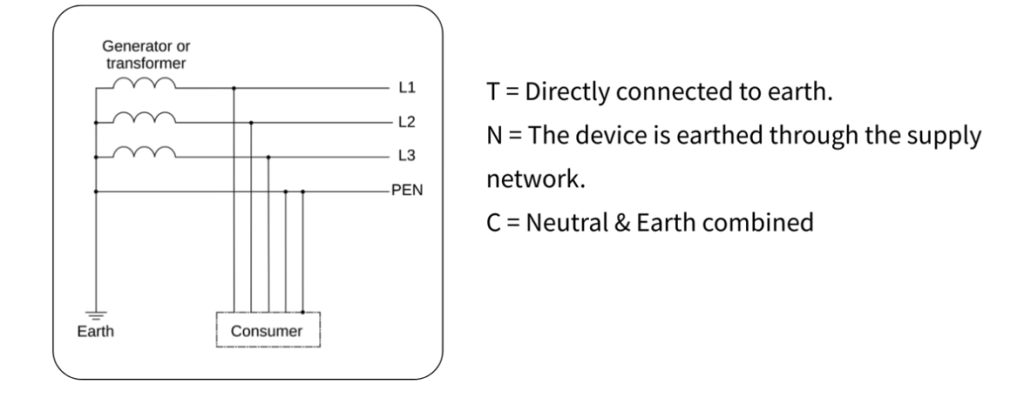
First, decode the letters.
- T – Source neutral directly connected to earth
- N – Equipment bodies connected to supply neutral
- C – Neutral and protective earth combined
In this system, neutral and earth share one conductor called PEN.
Instead of two separate wires, the system uses one shared conductor. This reduces installation cost. Utilities sometimes use this system in distribution networks.
However, this design introduces serious risks.
If the PEN conductor breaks upstream, equipment bodies can become live. The failure may occur far from the installation. Yet the danger still reaches the consumer.
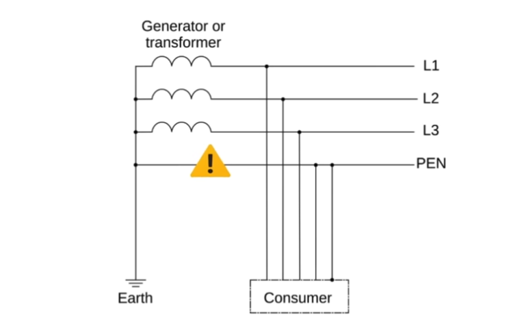
Consider a small workshop connected through a TN-C supply. A loose connection develops in the PEN conductor near the pole. Now metal parts inside the workshop may reach phase voltage.
These parts may include:
- Motor housings
- Panel enclosures
- Machine casings
Touching the equipment body completes the circuit. This can lead to electric shock.
Because of this risk, pure TN-C systems are rarely allowed inside buildings. They may appear in distribution networks, but they are not recommended within installations.
The main issue is clear. There is no dedicated protective conductor. If the combined conductor fails, the safety path fails as well.
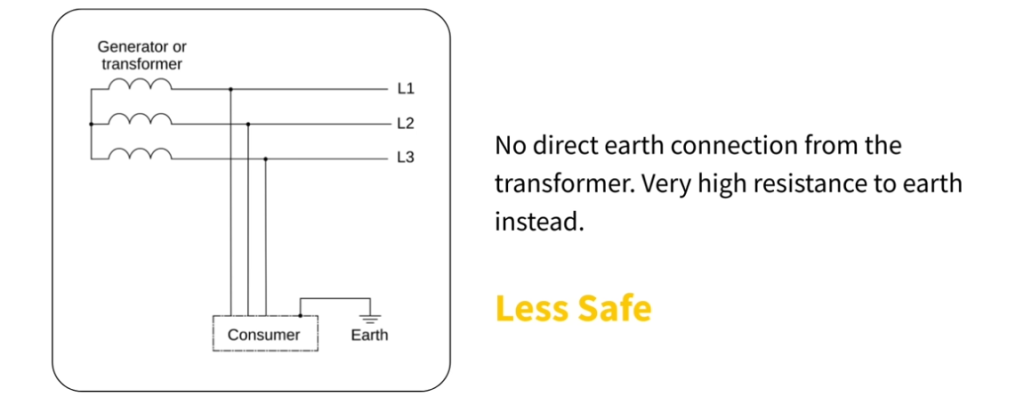
TT System in Types of Earthing Systems
The TT system improves safety compared with TN-C.
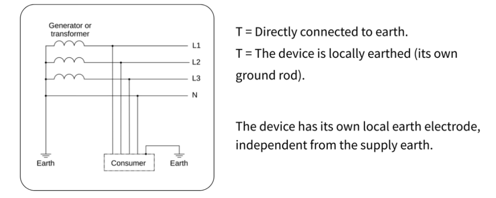
Here, the source neutral remains earthed. That explains the first letter T.
The exposed conductive parts connect to a separate local earth electrode. Therefore, the second letter is also T.
In this arrangement, each installation has its own earth pit. Equipment bodies connect directly to that local electrode.
This design appears safer.
For example, consider a rural farmhouse supplied by a utility line. The utility provides phase and neutral conductors. The homeowner installs an earth pit on the property.
All equipment bodies connect to that local earth pit.
However, the TT system introduces another challenge.
During a fault, current must return through the soil to the transformer neutral. Soil resistance is usually high. Therefore, the fault loop impedance becomes high.
Because of this, the fault current may remain too small.
If the current is small, the MCB may not trip quickly. That means a fault may remain in the system longer.
For this reason, TT systems depend heavily on RCCB protection.
The RCCB detects leakage current and disconnects the circuit quickly.
If the RCCB fails or gets bypassed, safety reduces significantly.
So compared with TN-C, TT removes the combined conductor risk. However, it strongly depends on:
- RCCB operation
- Soil resistivity
- Earth electrode quality
TN-C-S System in Types of Earthing Systems
The TN-C-S system offers a practical balance between safety and cost.
Let us decode its letters.
- T – Source neutral connected to earth
- N – Equipment connected to supply neutral
- C – Combined conductor in part of the system
- S – Separate conductors afterward
In this system, neutral and earth remain combined initially. After a certain point, they become separate.
This arrangement is called Protective Multiple Earthing (PME).
From the transformer to the service entry, a PEN conductor is used. Inside the building, the neutral and earth become separate conductors.
This configuration is very common in urban residential buildings.
Inside the installation, equipment bodies connect to a dedicated protective earth conductor. When a phase touches the equipment body, fault current returns through a low-impedance metallic path.
Because this path has low resistance, protective devices trip quickly.
This makes the TN-C-S system safer than TT for fault clearing.
However, one concern still exists.
If the PEN conductor breaks before the separation point, dangerous voltage may appear in the installation.
Therefore, TN-C-S still depends partly on upstream conductor integrity.
Despite this limitation, it remains one of the most widely used earthing systems today.
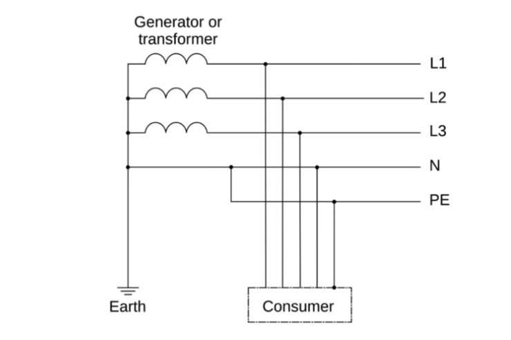
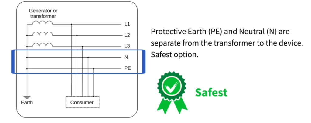
TN-S System in Types of Earthing Systems
The TN-S system is considered the safest arrangement among TN systems.
In this system, neutral and protective earth remain separate from the transformer itself. There is no combined PEN conductor anywhere in the network.
From the transformer secondary winding:
- One conductor carries neutral current
- Another conductor serves as protective earth
Because the conductors remain separate, the risk of combined conductor failure disappears.
Fault current returns through a dedicated low-impedance path. Protective devices operate faster and more reliably.
This arrangement significantly reduces touch voltage risk.
For that reason, TN-S systems are often used in:
- Large industrial plants
- Hospitals
- Data centers
- Sensitive control installations
However, TN-S has one drawback.
The system requires an additional conductor from source to load. Over long distances, this increases installation cost.
Despite the higher cost, TN-S offers excellent safety and electromagnetic performance.
IT System in Types of Earthing Systems
The IT system works differently from the other earthing arrangements.
In this configuration, the source remains isolated from earth. Sometimes it connects through high impedance instead of direct grounding.
However, exposed conductive parts remain connected to earth electrodes.
The IT system offers a unique advantage.
When a single phase-to-earth fault occurs, the system does not trip immediately. The supply continues operating.
This characteristic makes the IT system valuable in critical applications.
Common applications include:
- Hospitals and operating rooms
- Mines
- Critical process industries
However, IT systems require additional monitoring.
Special devices called insulation monitoring devices detect the first fault. Maintenance teams can then locate and fix the issue before a second fault occurs.
Because of this complexity, IT systems are not common in general distribution networks. They mainly appear in installations requiring uninterrupted power.
Comparison of Different Types of Earthing Systems
Understanding the differences between the types of earthing systems becomes easier when you compare them side by side.
| Earthing System | Conductor Arrangement | Fault Current Path | Safety Level | Common Applications |
| TN-C | Neutral and earth combined in one PEN conductor | Returns through the combined PEN conductor | Lowest safety among TN systems | Utility distribution networks |
| TT | Neutral from supply, local earth electrode at installation | Returns through soil to transformer neutral | Safer than TN-C but depends on RCCB | Rural houses and small installations |
| TN-C-S | Combined PEN conductor first, then separate N and PE | Returns through low-impedance metallic earth path | Good balance of safety and cost | Urban residential installations |
| TN-S | Neutral and protective earth fully separate from source | Returns through dedicated protective conductor | Highest safety among TN systems | Hospitals, industries, data centers |
| IT | Source isolated from earth, exposed parts earthed | Fault current limited due to isolation | Best for supply continuity | Hospitals, mines, critical processes |
Conclusion
Understanding the types of earthing systems is essential for every electrical engineer. Earthing design determines how fault current flows in a system.
It also determines how quickly protective devices operate.
If we rank these systems from least safe to most robust, the order becomes clear:
- TN-C – Highest risk due to combined conductor
- TT – Safer but dependent on RCCB and soil conditions
- TN-C-S – Balanced solution widely used in installations
- TN-S – Best standard practice for safety and performance
- IT – Best for continuity of supply in critical applications
Earthing is not simply about driving a rod into the ground. It defines the entire fault path in an electrical system.
A well-designed earthing system ensures faults clear quickly and safely.
For a clearer practical understanding, watching the detailed video explanation will reinforce these concepts even further.
