
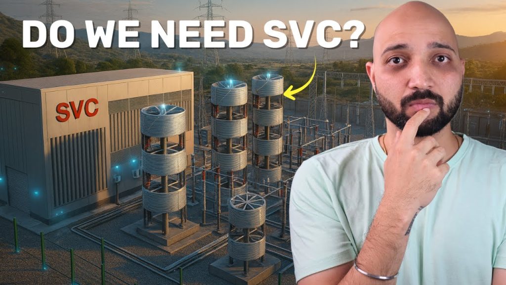
Static VAR Compensator
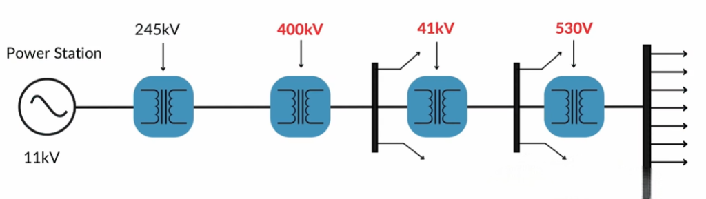
Static VAR Compensator https://www.theelectricalguy.in/wp-content/uploads/2025/09/maxresdefault-1-1-1024x576.jpg 1024 576 Gaurav Joshi https://secure.gravatar.com/avatar/f6a3006f3f7233a71d79d0e705c167ae12516870e5239627478665ae377435b3?s=96&d=mm&r=gIn a power system, voltage control is very important. If the voltage is not controlled, the system may face serious problems. For example, a generating station may send 245 kV. At the receiving end, the voltage should also stay near 245 kV. But if the receiving end shows 400 kV, then that is a problem.
This does not only affect substations. It also impacts consumers. That is why we must control and maintain voltage in power systems. This is where the Static VAR Compensator becomes essential.
Table of Contents
- Why Voltage Control Matters
- Example with Simulation
- Shunt Reactors in Power Systems
- The Limitation of Shunt Reactors
- The Switching Problem
- Static VAR Compensator as a Solution
- How Static VAR Compensator Works
- Benefits of Static VAR Compensator
- Other Voltage Control Methods
- Conclusion
Why Voltage Control Matters
When transmission lines are long, voltage issues occur. This is a regular situation in power systems. If the load on the line is low, the voltage at the receiving end rises sharply.
For instance, a sending end of 245 kV may rise to 400 kV at the receiving end. This is called the Ferranti effect. It happens because with insufficient load, inductive reactance is low. As a result, the capacitive effect dominates. The voltage then rises to a very high level.
On the other hand, when load increases beyond a limit, the opposite occurs. Inductive reactance dominates. Capacitive support is short. The voltage drops below the sending level. This is also harmful.
Example with Simulation
Consider a simple transmission line model. If the line is lightly loaded, the voltage at the receiving end becomes very high. For example, a sending end of 353 kV may result in 522 kV at the receiving end.
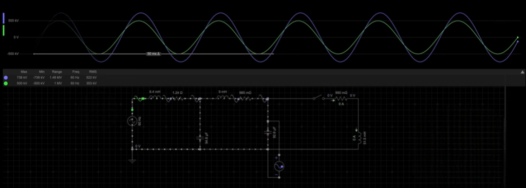
Substation equipment cannot handle such large deviations. They are designed for 353 kV with some tolerance. This problem cascades through the entire system. Adding load reduces the issue, but loads keep changing.
Shunt Reactors in Power Systems
One known solution is to add shunt reactors. These add inductive reactance. The inductive and capacitive effects then balance each other. This limits the reactive power and keeps voltage under control.
When a shunt reactor is added, the sending and receiving end voltages become almost equal. This works when the system is lightly loaded.
The Limitation of Shunt Reactors
Problems occur when the load returns. If a reactor remains in the system, voltage drops below the required level. This creates trouble. Motors may not work properly. Equipment may misoperate.
The solution seems simple: add capacitors when inductive effect dominates or disconnect the reactor when load is high. Both options balance voltage again.
But there are issues. Transmission line loads change often. Morning, evening, and night loads all differ. Switching reactors and capacitors frequently is not easy. Circuit breakers used for switching are not designed for repeated operations.
The Switching Problem
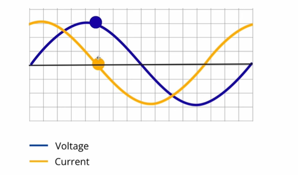
Inductive and capacitive elements have voltage and current out of phase by 90 degrees. Circuit breakers usually switch at current zero. At this point, the voltage across inductors or capacitors is at its maximum.
This can cause restriking in the breaker. Controlled switching devices (CSD) can help by finding the right moment to switch. Still, frequent operations are not suitable for breakers.
If reactors remain in the system continuously, they reduce power transmission capacity. These issues make shunt reactors and capacitors less effective for dynamic voltage control.
Static VAR Compensator as a Solution
The Static VAR Compensator solves these problems. It still uses inductors and capacitors. But instead of circuit breakers, it uses thyristors for switching.
Power electronics allow thyristors to switch many times without issues. The compensator senses voltage and reactive power in the system. It then performs switching automatically. Operators do not need to take manual actions.
How Static VAR Compensator Works
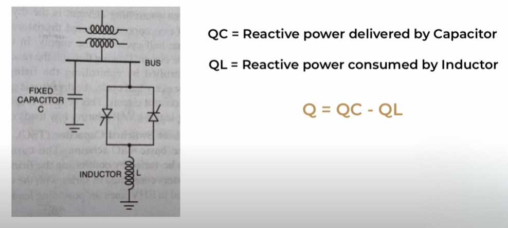
In a simple Static VAR Compensator arrangement, the inductor connects through thyristors. The capacitors are fixed. By changing the firing angle of the thyristors, the inductor current can be controlled.
Reactive power is the key to voltage control. Voltage control is basically reactive power control. If we control reactive power, we also control voltage.
Let’s denote QL as reactive power consumed by the inductor. QC is reactive power delivered by the capacitor. The resultant reactive power Q equals QC minus QL. By controlling QL through thyristors, the total reactive power is controlled.
Some designs use thyristor-controlled capacitors and fixed reactors. Both arrangements achieve the same purpose. They provide fine control of reactive power and voltage.
Benefits of Static VAR Compensator
The Static VAR Compensator offers several advantages:
- It improves voltage stability.
- It increases the power transmission capacity of the line.
- It allows automatic, frequent, and smooth switching.
- It avoids the limitations of reactors and capacitors.
The name explains its role. “Static” means no rotating parts are used. “VAR” refers to reactive power. “Compensator” shows that it balances reactive power for voltage regulation.
Other Voltage Control Methods
There are other methods to control voltage in a power system. These include:
- Excitation control and voltage regulators at the generator.
- Tap changing transformers.
- Booster transformers.
- Shunt reactors and capacitors.
- Static VAR Compensator.
- Synchronous condensers.
Conclusion
Voltage control in a power system is critical. Shunt reactors and capacitors work but face switching problems. They cannot handle frequent load changes well.
The Static VAR Compensator uses thyristors for smooth switching. It controls reactive power automatically. This stabilizes voltage and improves power transmission.
For a better understanding, you can watch the detailed video explanation linked.
