

Low Voltage Switchgear: Internal Separation Form
Low Voltage Switchgear: Internal Separation Form https://www.theelectricalguy.in/wp-content/uploads/2025/10/maxresdefault-3-1024x576.jpg 1024 576 Gaurav Joshi https://secure.gravatar.com/avatar/f6a3006f3f7233a71d79d0e705c167ae12516870e5239627478665ae377435b3?s=96&d=mm&r=gImagine this, an engineer is working on low voltage switchgear maintenance. During the process, he accidentally touches a live part. The result could be dangerous, even life-threatening. However, this risk can be reduced with the help of internal separation forms.

Internal separation forms in low voltage switchgear are crucial for safety. They define how much protection a switchgear provides to people working near it. Let’s explore what internal separation forms are and the different types defined by the IEC standard.
Table of Contents
- What Is an Internal Separation Form in Low Voltage Switchgear
- Purpose of Internal Separation Forms
- Understanding the Four Forms of Internal Separation
- Subcategories of Internal Separation Forms
- Choosing the Right Form of Separation
- Importance of Safety in Switchgear Systems
- Learning More About Low Voltage Switchgear
- Summary of Internal Separation Forms
- Practical Example
- Conclusion
What Is an Internal Separation Form in Low Voltage Switchgear
In low voltage switchgear, an internal separation form refers to the physical separation between bus bars, functional units, and terminals. These separations are achieved using barriers or partitions.
As the name suggests, the purpose of internal separation is to separate internal components. Inside a switchgear, there are several components: air circuit breakers, MCBs, MCCBs, and bus bars. Using insulating barriers, such as plastic or metal partitions, these components are divided into sections.
These barriers are called internal separation forms. They prevent accidental contact with live parts and isolate components from each other.
Purpose of Internal Separation Forms
The main purpose of internal separation forms is safety. They protect engineers and maintenance staff working around the switchgear.
Besides safety, these separations also help limit faults. If a fault occurs inside one compartment, internal barriers stop it from spreading to other sections. This ensures the system keeps running even during maintenance or minor faults.
Safety always comes first. Human life is more valuable than any machinery. The IEC standard has therefore defined four forms of internal separation. These are Form 1, Form 2, Form 3, and Form 4.
Form 1 provides the least safety, while Form 4 offers the highest. The selection of the form depends on where and how the switchgear is used. For example, if a plant cannot afford downtime, Form 4 is ideal since it provides maximum safety.
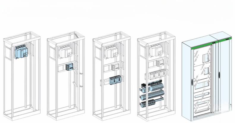
Understanding the Four Forms of Internal Separation
To understand internal separation forms better, let’s look at each of the four forms defined by the IEC standard, from Form 1 to Form 4.
Form 1: No Internal Separation
Form 1 has no internal separation inside the switchgear.
This means all parts like bus bars and functional units are open and exposed. The bus bars are not covered, and anyone can touch them. There are no barriers or partitions between the components.
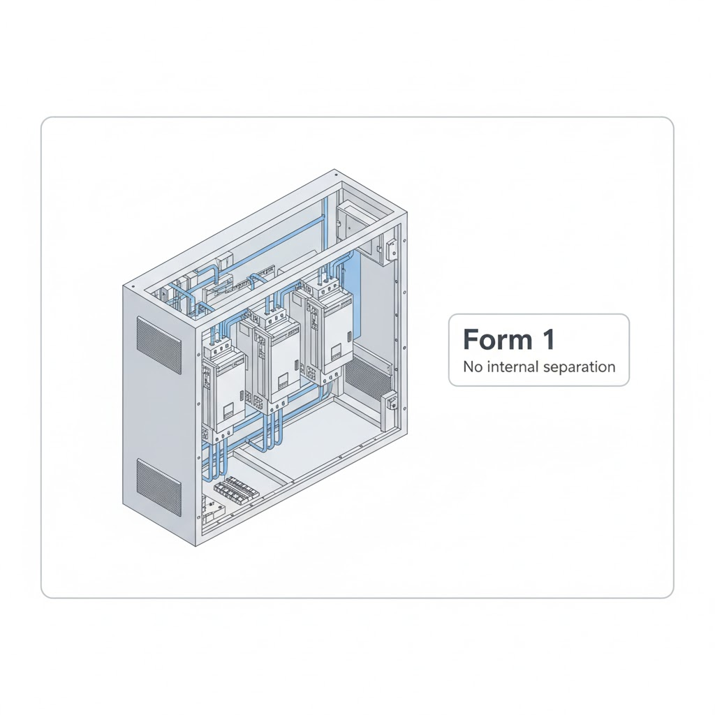
This is the simplest form and provides the least safety. It is suitable only for low-risk environments where maintenance or operation is not frequent.
Form 2: Separation Between Bus Bars and Functional Units
In Form 2, there is a separation between horizontal and vertical bus bars and functional units.
Here, barriers or partitions made of sheet steel, stainless steel, or insulating plastic cover the bus bars. These materials depend on the type-tested design of the switchgear.
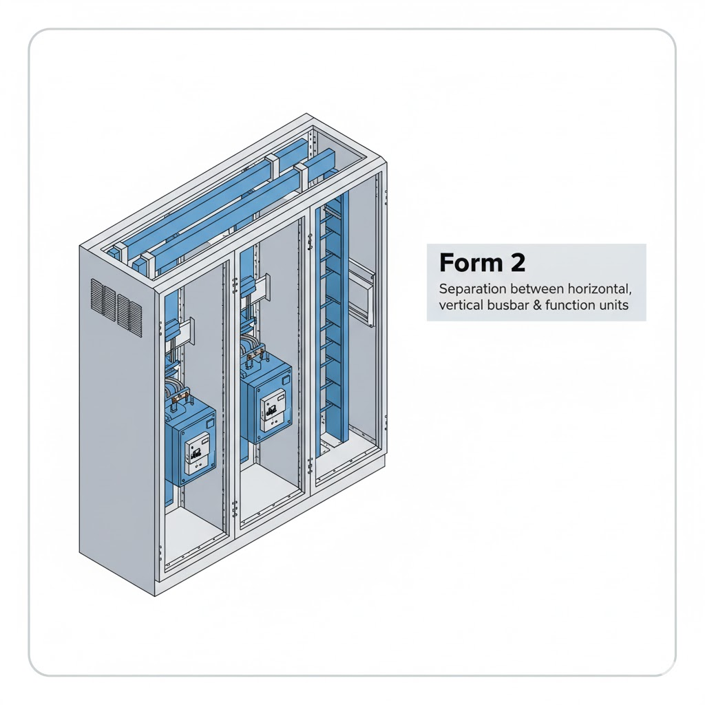
If we compare it to Form 1, we can see the difference clearly. In Form 1, the bus bars are open. In Form 2, they are enclosed and separated from functional units.
This reduces the risk of accidental contact and increases safety.
Form 3: Separation of Functional Units
Form 3 provides more safety than Form 2.
In Form 3, the switchgear must have Form 2 separation plus separation of functional units from each other.

Each functional unit, such as an MCCB or MCB, is separated by barriers. For example, if one functional unit needs maintenance, the others remain unaffected.
Let’s compare it again. In Form 2, there are no separations between functional units. In Form 3, each unit is clearly separated. This means if one unit fails, the others continue to work safely.
So, Form 3 = Form 2 + separation of functional units.
This form provides a higher level of safety and is suitable for plants where continuous operation is important.
Form 4: Maximum Safety and Separation
Form 4 provides the highest level of safety among all forms.
It includes all the features of Form 3 plus separation of terminals of functional units from one another.
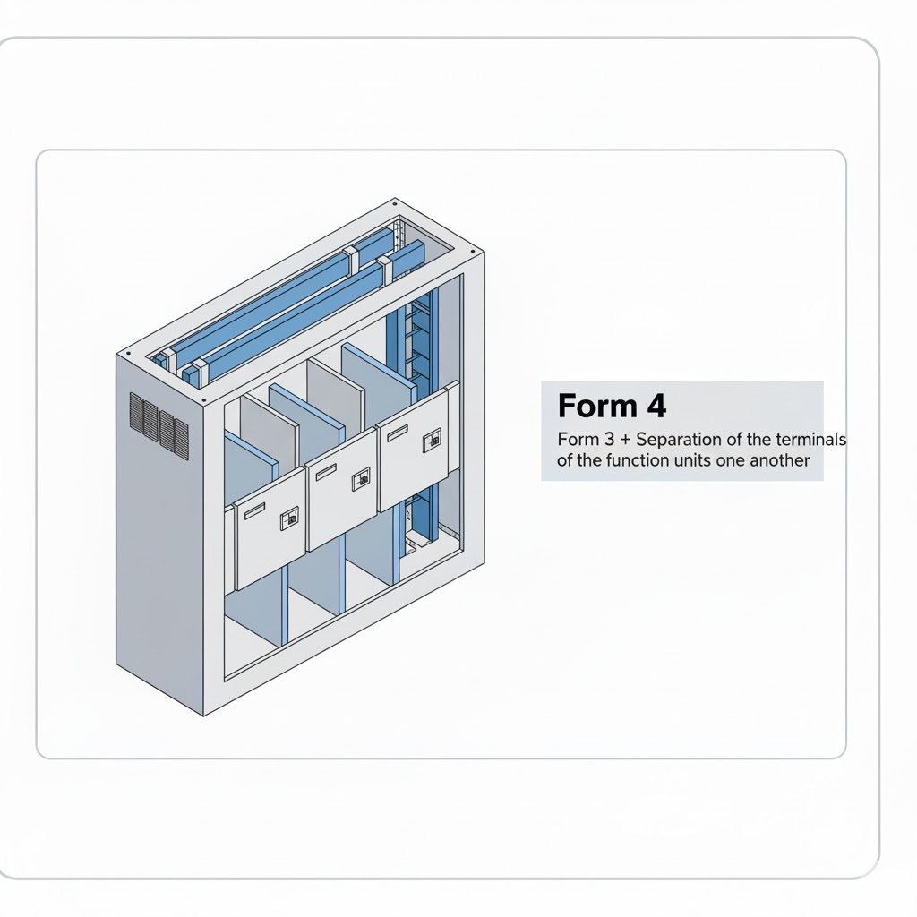
Let’s focus on the terminals. In Form 3, terminals are still open. But in Form 4, terminals are completely separated by barriers. Each terminal has its own insulated compartment.
This means every bus bar, functional unit, and terminal is separated.
If we look closely, we can see that Form 4 offers maximum protection. Even during maintenance or fault conditions, engineers can safely work on one part without affecting others.
So,
Form 4 = Form 3 + separation of terminals of functional units.
Form 4 not only ensures safety but also improves reliability. However, this increased protection also raises the cost of the switchgear.
Subcategories of Internal Separation Forms
Within Form 4, there are also subcategories like Form 4A and Form 4B. These specify more detailed separation conditions.
However, these belong to advanced-level understanding and are not covered here. They are part of the next level of study usually covered in a Level 2 switchgear course.
For now, remember that Forms 1 to 4 are the main types defined by the IEC standard.
Choosing the Right Form of Separation
Choosing the correct internal separation form depends on the application and environment.
Form 1 may be enough for small, low-risk installations. But for industrial plants, the risk is higher. Power interruptions can cause heavy financial losses.
Therefore, Form 3 or Form 4 is preferred for industries like:
- Power plants
- Steel manufacturing units
- Oil and gas industries
In such environments, 99% of switchgear systems use at least Form 3. This allows maintenance work without shutting down the entire system.
Workers can replace or repair a faulty part while keeping the rest of the system live. This saves both time and money and, most importantly, ensures safety.
Importance of Safety in Switchgear Systems
Safety is the top priority in switchgear design. Internal separation forms play a big role in achieving that.
For example, during maintenance or testing, separated compartments prevent accidental electric contact. They also stop faults from spreading, ensuring that the power supply continues.
In industries like oil and gas, even one hour of power loss can cost millions. With higher separation forms like Form 3 or Form 4, this risk is reduced.
So, while higher forms may cost more, the protection and operational benefits make them worth it.
Learning More About Low Voltage Switchgear
If you are new to this topic, it’s important to build a solid foundation. The Low Voltage Switchgear Level 1 course helps learners understand all the basics.
This course covers:
- Basic concepts of low voltage switchgear
- Common terminology
- Types of configurations
- IEC standards
Once you’ve mastered the fundamentals in Level 1, the Low Voltage Switchgear Level 2 course takes you a step further. It dives deeper into detailed design, protection coordination, component selection, and system integration. You’ll learn how to interpret technical drawings, assess fault levels, and apply IEC standards in real-world projects.
Summary of Internal Separation Forms
Here’s a quick summary of all four forms for better understanding:
| Form | Description | Level of Safety |
| Form 1 | No internal separation | Lowest |
| Form 2 | Separation between bus bars and functional units | Moderate |
| Form 3 | Form 2 + separation of functional units from each other | High |
| Form 4 | Form 3 + separation of terminals of functional units | Highest |
Each form increases safety and protection compared to the previous one.
Practical Example
Let’s consider an industrial example. In a steel plant, maintenance is frequent. If a circuit breaker needs replacement, the plant cannot stop production.
If the switchgear is built with Form 3 or Form 4, the engineer can safely isolate and replace one component without affecting the rest.
But if the system uses Form 1, maintenance becomes risky and may cause downtime. Hence, choosing the correct form ensures both safety and efficiency.
Conclusion
Internal separation forms in low voltage switchgear are essential for ensuring safety and preventing electrical faults from spreading.
Form 1 offers the least protection, while Form 4 ensures maximum safety with complete separation of all internal components. The right choice depends on the environment, safety needs, and operational requirements.
For industries where downtime is costly, Forms 3 and 4 are preferred. Although these forms increase costs, they also increase protection, reliability, and operational continuity.
To understand this concept visually and clearly, watch the video “Low Voltage Switchgear: Internal Separation Form” by TheElectricalGuy on YouTube. It provides a complete demonstration of each form and helps you grasp the topic better.
