
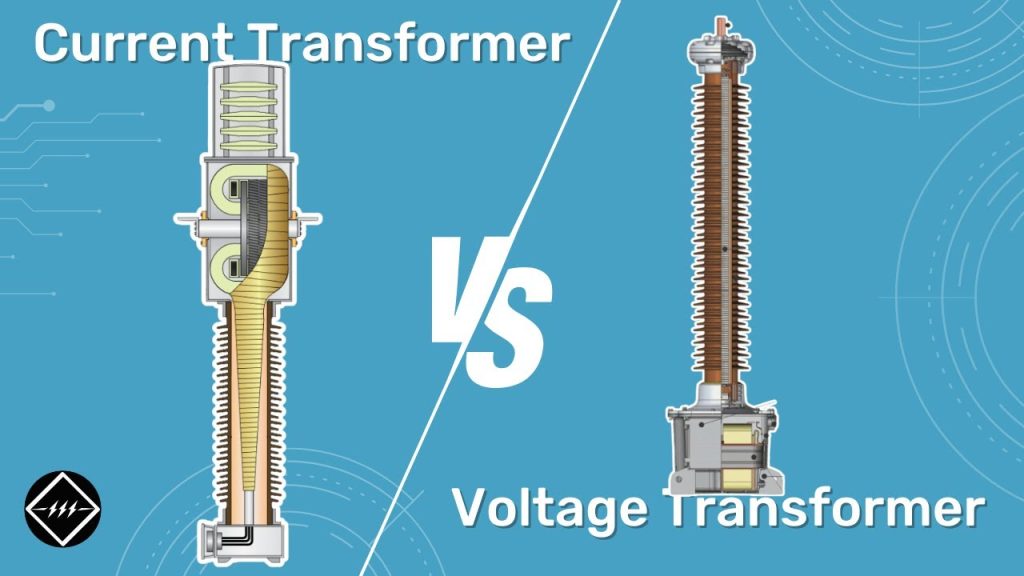
CT vs VT: What’s the Difference Between Current Transformer and Voltage Transformer?
CT vs VT: What’s the Difference Between Current Transformer and Voltage Transformer? https://www.theelectricalguy.in/wp-content/uploads/2026/02/maxresdefault-3-2-1024x576.jpg 1024 576 Gaurav Joshi https://secure.gravatar.com/avatar/f6a3006f3f7233a71d79d0e705c167ae12516870e5239627478665ae377435b3?s=96&d=mm&r=gCurrent transformer and voltage transformer are two major types of instrument transformers used in power systems. Many engineers often get confused between them. In this article, we will clearly explain CT vs VT using six important parameters.

Both devices play a vital role in measurement and protection. However, their purpose, construction, connection, and behavior are different. Once you understand these differences, identifying them in a substation becomes easy.
Let us start with their purpose.
Table of Contents
- Purpose of Current Transformer and Voltage Transformer
- Voltage and Current Behavior in CT vs VT
- Construction Differences Between CT and VT
- Connection in Substations: Series vs Phase-to-Earth
- Primary Current Dependency in CT vs VT
- Accuracy Classes as per IEC Standards
- Summary of CT vs VT Differences
- Conclusion
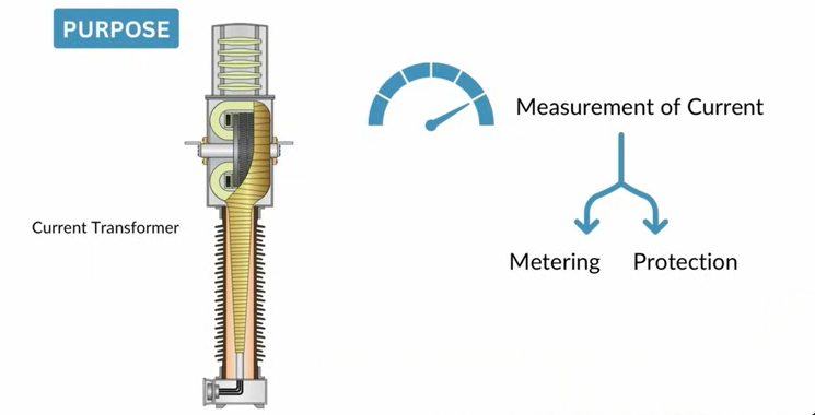
Purpose of CT vs VT
When discussing CT vs VT, the first difference lies in their purpose. A current transformer measures current flowing in the system. In transmission and distribution networks, current levels are very high. They can reach 2000, 4000, or even 6000 ampere. Measuring such high current directly is not practical.
Instead of building large meters, we use a transformer to step down the current. A current transformer reduces the high primary current to a safe secondary value. This value is usually 1 ampere or 5 ampere.
The measured current serves two purposes. First, it supports metering. If power is sold or purchased, current must be measured for billing. Second, it supports protection. The CT sends current signals to relays to detect faults.
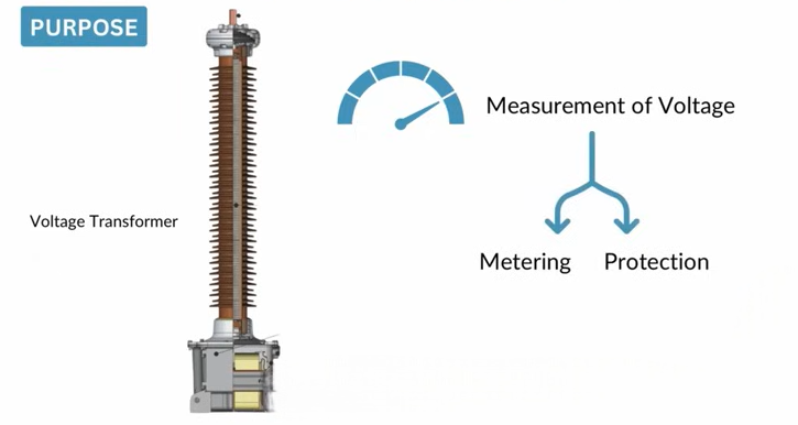
Now let us look at the voltage transformer. The idea is similar. In high voltage systems, measuring voltage directly is not safe. Voltage can reach hundreds of kilovolts. A voltage transformer steps down high voltage to a measurable level. The secondary voltage is typically 110 volts. This reduced voltage is supplied to meters and relays.
So in CT vs VT, CT measures current and VT measures voltage. Both support metering and protection. However, one works on current and the other on voltage.
Voltage and Current Behavior in CT vs VT
The second major difference in CT vs VT is the behavior of voltage and current. In a current transformer, current is stepped down. When current decreases, voltage increases proportionally. This follows transformer principles.
On the other hand, in a voltage transformer, voltage is stepped down. As voltage decreases, current increases on the secondary side. Therefore, in CT, current reduces and voltage rises. In VT, voltage reduces and current rises. This is a fundamental electrical difference between the two.
Construction Difference in CT vs VT
Construction also differs in CT vs VT. In a current transformer, there is usually no dedicated primary winding. The conductor whose current we want to measure acts as the primary. This conductor passes through the CT core. The primary side typically has one turn. In some cases, it may have two or three turns. However, most installations use a single turn.
Engineers wind the secondary winding around the core in a current transformer. This winding produces the reduced current output. In contrast, manufacturers design voltage transformers differently. They provide a dedicated primary winding and a dedicated secondary winding. They insulate both windings properly and design them according to the required voltage levels.
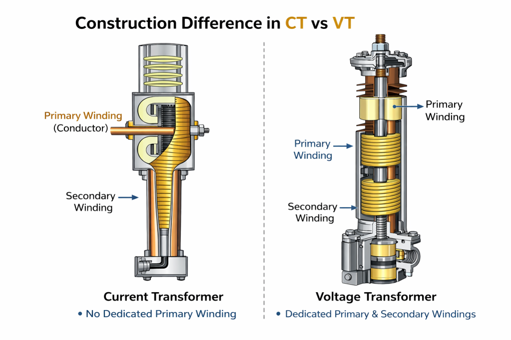
There is also a special type of voltage transformer called a capacitive voltage transformer. It is commonly used in high and extra high voltage substations. In this design, capacitors divide the voltage before measurement. Thus, CT construction is simpler with no dedicated primary coil. VT construction includes both primary and secondary windings.
Connection Difference in CT vs VT
Another clear difference in CT vs VT appears in their system connection. Engineers always connect a current transformer in series with the line. The transmission conductor passes directly through the CT. As a result, you can clearly see an incoming and an outgoing connection.
If you notice an instrument transformer with a defined input and output line, you can identify it as a CT. Because it operates in series with the system, engineers also call it a series transformer.
In contrast, engineers connect a voltage transformer between phase and earth. They do not provide a dedicated outgoing conductor. This connection method clearly distinguishes a VT from a CT.
Usually, a dropper connects the busbar to the VT. The other end connects to ground. So if you observe only a phase-to-earth connection without an outgoing conductor, you are likely looking at a VT. This visual identification helps engineers quickly distinguish between CT vs VT in substations.
Primary Current Dependency in CT vs VT
Primary current behavior creates another important difference in CT vs VT. In a current transformer, the primary current does not depend on the secondary. Since the CT is connected in series, primary current always flows.
Even if the secondary is open or short-circuited, the primary still carries system current. This is because the transmission line remains active. That is also the reason why CT secondary must never be left open. An open secondary can cause dangerously high voltage.
In contrast, in a voltage transformer, the primary current depends on the secondary. Any change on the secondary side affects the primary side. Therefore, CT primary current is independent of secondary load. VT primary current is influenced by secondary conditions. This difference plays a major role in safety and operation.
Accuracy Classes in CT vs VT
The final major comparison in CT vs VT is accuracy class. These classes are defined by IEC standards. Both transformers support metering and protection. Hence, both have separate cores for each purpose.
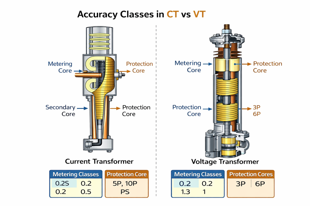
In current transformers, protection classes include 5P, 10P, and PS. Metering classes include 0.2S, 0.2, 0.5, and 1. Among these, 0.2S is one of the most accurate metering classes. Protection classes focus on fault performance rather than high precision.
Voltage transformers also have defined classes. For protection, classes include 3P and 6P. For metering, classes include 0.2, 0.5, 1, and 3. Again, 0.2 is among the most accurate metering classes for VT.
While both devices have metering and protection accuracy, the class designations differ. Thus, accuracy classification forms another key difference in CT vs VT.
Summary of CT vs VT Differences
Let us quickly summarize the differences discussed. A current transformer measures high current and steps it down. A voltage transformer measures high voltage and reduces it. In CT, current decreases and voltage increases. In VT, voltage decreases and current increases.
CT has no dedicated primary winding. VT has both primary and secondary windings. CT connects in series with incoming and outgoing conductors. VT connects between phase and earth. Primary current in CT does not depend on secondary conditions. In VT, primary current depends on secondary load.
Accuracy classes differ for CT and VT as defined by IEC standards. Each device serves a specific function in the power system. Both are essential. However, their operation and design are distinct.
Conclusion
Understanding CT vs VT is essential for every electrical engineer. These instrument transformers play a crucial role in measurement and protection. CT helps measure high current safely. VT helps measure high voltage safely. Although both reduce electrical quantities, their behavior, construction, and connection differ.
Recognizing these differences improves technical clarity. It also helps during interviews and site inspections. If you want a clearer visual understanding of CT vs VT, watching the detailed explanation video will help reinforce these concepts further. Keep learning and keep exploring power system fundamentals.
