

What are 5P10 & 5P20 in CTs? Complete Guide to Protection Accuracy Classes
What are 5P10 & 5P20 in CTs? Complete Guide to Protection Accuracy Classes https://www.theelectricalguy.in/wp-content/uploads/2026/02/maxresdefault-3-1-1024x576.jpg 1024 576 Gaurav Joshi https://secure.gravatar.com/avatar/f6a3006f3f7233a71d79d0e705c167ae12516870e5239627478665ae377435b3?s=96&d=mm&r=gIf you have ever checked the nameplate of a current transformer, you may have noticed markings like 5P20 15VA. At first glance, these symbols may look confusing. However, they carry important technical meaning. They explain how a current transformer behaves during fault conditions and how accurate it remains at high currents.
These markings are directly related to protection performance. They help engineers understand whether a CT can support relays during short circuits. This is where 5P10 & 5P20 in CTs become important.
In this article, we will explain what 5P10 and 5P20 mean, how they are defined, and where they are used. The explanation follows industry practice and IEC standards. It uses simple language for easy understanding.
Table of Contents
- Introduction to Protection Accuracy in Current Transformers
- Understanding the Meaning of 5P10 & 5P20 in CTs
- Composite Error and Its Role in Protection Performance
- Accuracy Limit Factor and Burden Considerations
- Practical Applications of 5P10 and 5P20 Classes
- Summary and Conclusion
Introduction to Protection Accuracy in Current Transformers
Current transformers perform two major functions. First, they supply current to meters for measurement. Second, they provide input to protection relays during faults. These two functions require different operating behavior.
Meters need accurate readings under normal conditions. Protection relays need reliable signals during abnormal conditions. Because of this, most CTs contain separate cores. One core serves metering. Another core serves protection.
Protection cores are designed to work under high fault currents. They must not saturate easily. If they saturate, relays will not receive correct signals. As a result, faults may not clear on time.
The terms 5P10 & 5P20 in CTs apply only to these protection cores. They do not relate to metering cores. This is the first point every engineer must remember.
Understanding the Meaning of 5P10 & 5P20 in CTs
Let us now understand what each part of 5P10 and 5P20 represents. A typical CT marking looks like this: 5P20 15VA. Each part has a specific meaning.
The first number shows the composite error limit. The letter P stands for protection. The last number shows the accuracy limit factor. The VA value shows the burden capacity. So, when a CT is marked as 5P20, it means:
The composite error is less than 5 percent.
The core is meant for protection.
The CT remains accurate up to 20 times rated current.
Similarly, 10P20 means:
The composite error is less than 10 percent.
The core is meant for protection.
The CT remains accurate up to 20 times rated current.
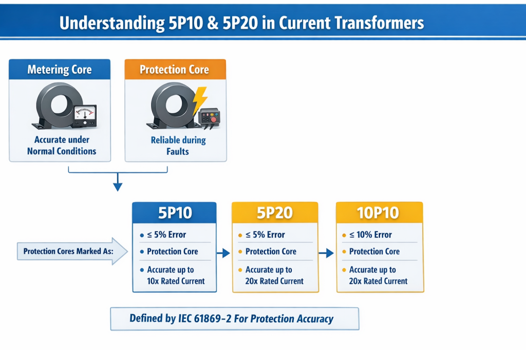
These values are defined by IEC 61869-2. Manufacturers must follow these limits during testing. Therefore, 5P10 & 5P20 in CTs describe how a protection core behaves during faults.
Composite Error and Its Importance in Protection CTs
The first number in 5P and 10P represents composite error. Composite error measures how much the CT output deviates during fault conditions. This error is based on instantaneous values. It does not use average values. Instead, it checks current at specific moments of the waveform.
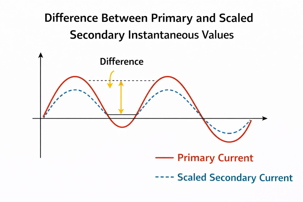
In simple terms, composite error is the difference between the actual primary current and the transformed secondary current multiplied by the rated ratio. Because it uses instantaneous values, it shows real CT behavior during short circuits. This makes it very important for protection systems.
When a CT is marked as 5P, it keeps the composite error below 5 percent. When it is marked as 10P, it keeps the error below 10 percent. This means 5P CTs are more accurate than 10P CTs under fault conditions. However, both are suitable for protection when selected properly.
Accuracy Limit Factor and Burden in 5P10 & 5P20 in CTs
The last number in 5P10 and 5P20 is called the accuracy limit factor, also known as ALF. Accuracy limit factor shows how much current the CT can handle without losing accuracy.
For example, in 5P20, the ALF is 20. This means the CT can maintain accuracy up to 20 times its rated current. If a CT has a rated current of 2000 A and ALF is 20, it can handle:
20 × 2000 = 40,000 A
Even at this current, the composite error remains within limits. Beyond this value, saturation may occur. Higher ALF gives better fault performance. However, it also increases CT cost. Therefore, engineers must balance performance and budget.
Burden also plays a major role in accuracy. Burden is the total electrical load connected to the CT secondary. It includes relay resistance, cable resistance, and internal losses. The VA value on the nameplate shows the maximum burden the CT can handle. For example, 15VA means the CT can support up to 15 volt-ampere load.
Accuracy remains guaranteed only when the burden stays within this limit. If the burden increases, the composite error rises and saturation occurs earlier. Therefore, when selecting 5P10 and 5P20 in CTs, engineers must consider both the ALF and the burden together.
Applications and Practical Use of 5P10 & 5P20 in CTs
Protection accuracy classes are mainly used in overcurrent protection systems. Overcurrent relays detect excessive current and trip circuit breakers. For reliable operation, these relays need stable CT output during faults. That is why 5P and 10P classes are widely used.
Common applications include feeder protection, transformer backup protection, motor protection, and distribution system protection. 5P20 CTs are preferred in areas with high fault levels. They provide better stability during severe short circuits.
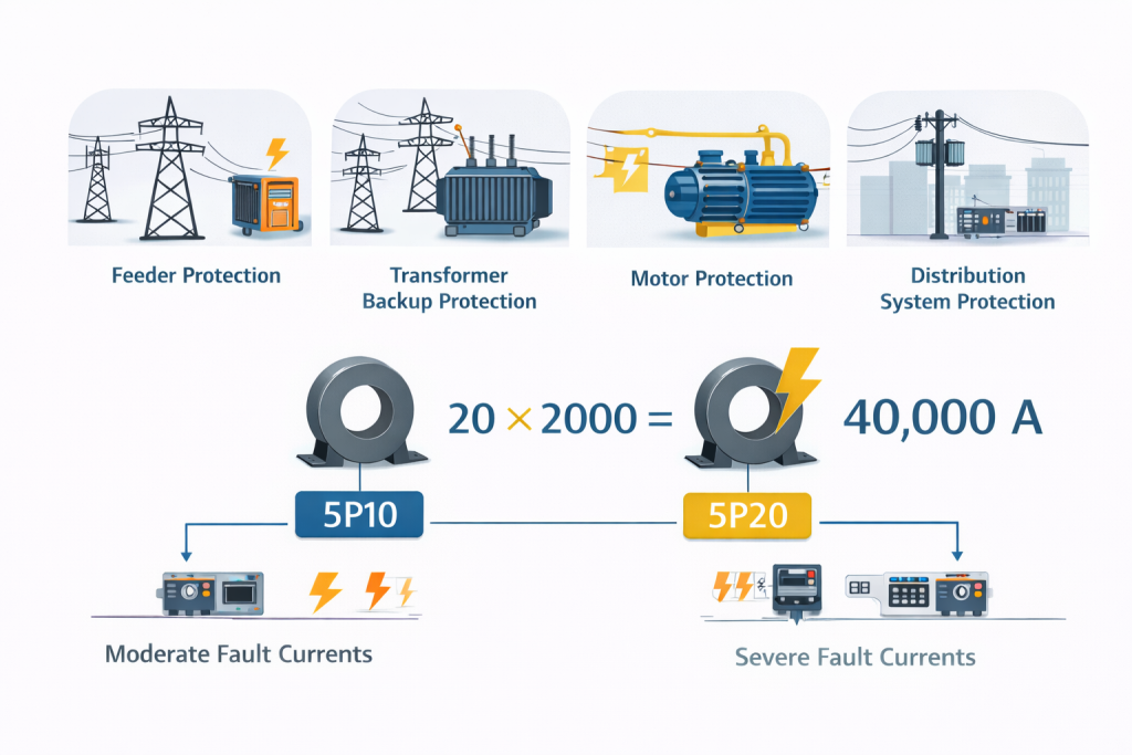
5P10 CTs are used where fault currents are moderate. They are suitable for less critical protection zones. Earlier, a 15P class also existed. However, IEC no longer defines limits for it. Therefore, it is obsolete today.
Manufacturers prove accuracy classes through type testing. During these tests, high currents and rated burden are applied. Composite error is measured. Only CTs that meet limits receive certification.
Correct selection is essential. Engineers must consider maximum fault current, relay sensitivity, cable length, burden value, and system voltage. Wrong selection leads to relay maloperation and safety risks.
Summary and Conclusion
The markings 5P10 & 5P20 in CTs define protection accuracy in current transformers. The first number shows composite error. The letter P shows protection use. The last number shows accuracy limit factor. The VA value shows burden capacity.
5P20 CTs can handle higher fault currents than 5P10 CTs. Both are defined by IEC standards and verified through testing. Their accuracy depends strongly on burden and system conditions. Understanding these parameters helps engineers design reliable protection systems. It improves safety, reduces false tripping, and prevents equipment damage.
For better practical understanding, watch the referenced video. It explains these concepts using clear examples and visual demonstrations.
