

Working Principle of Current Transformer: How CTs Measure High Current Safely
Working Principle of Current Transformer: How CTs Measure High Current Safely https://www.theelectricalguy.in/wp-content/uploads/2026/02/maxresdefault-2-1024x576.jpg 1024 576 Gaurav Joshi https://secure.gravatar.com/avatar/f6a3006f3f7233a71d79d0e705c167ae12516870e5239627478665ae377435b3?s=96&d=mm&r=gIn electrical power systems, transmission lines carry very high current. In many cases, this current reaches thousands of amperes. Such high current cannot be measured directly using normal meters. Direct measurement requires large equipment. It also increases cost and space requirements.
Because of this limitation, engineers use current transformers. A current transformer, or CT, reduces high current to a small value. This smaller value can be measured safely. It can also be used for protection purposes.
Through CTs, engineers monitor system performance. They also detect faults early. However, incorrect use of CTs can cause serious damage. Therefore, understanding their working principle is essential.
This article explains the principle of current transformer. It follows the same learning flow as the original masterclass.
Table of Contents
- Why High Current Measurement Needs Current Transformers
- Working Principle of Current Transformer Based on Faraday’s Law
- Understanding Working Principle Using a Regular Transformer Example
- Flux Interaction and Magnetic Balance in Transformers
- Power Balance and Current Relationship in Transformers
- Construction Difference Between Power Transformer and Current Transformer
- Series Connection Concept in Current Transformers
- Primary and Secondary Behavior in Current Transformers
- Practical Example: Normal Operating Condition of a CT
- Practical Example: Open-Circuited Secondary Condition
- Why Primary and Secondary Current Are Independent in CTs
- Key Differences Between Power Transformers and Current Transformers
- Summary of Working Principle of Current Transformer
- Conclusion
Why High Current Measurement Needs Current Transformers
In transmission and distribution systems, current levels are very high. They usually range from 1,000 A to 4,000 A. Sometimes, they go even higher. Such current is necessary for power delivery. However, it creates challenges for measurement.
If engineers try to measure this current directly, they need very large meters. These meters must carry the full current. As a result, they become bulky and expensive. Installation also becomes difficult.
Fortunately, transformers provide a better solution. They allow engineers to change current levels safely. By using transformer principles, high current can be reduced. After reduction, normal meters and relays can measure it easily.
This is where the current transformer becomes useful. It converts large current into a small standard value. This value can be connected directly to measuring devices.
Working Principle of Current Transformer Based on Faraday’s Law
The working principle of a current transformer comes from Faraday’s Law of electromagnetic induction. This law states that a changing magnetic field produces voltage in a nearby conductor. Every transformer works on this principle. Current transformers are no exception.
When alternating current flows in a conductor, it creates a magnetic field. This field changes continuously. Because of this change, magnetic flux develops in the core. Part of this flux links with the secondary winding.
Due to this linking, voltage appears in the secondary. Once voltage is present, secondary current starts flowing. This current passes through meters or relays. At the same time, not all flux links both windings. Some flux escapes into the air. This is called leakage flux. The remaining part is mutual flux. Mutual flux is responsible for energy transfer. In a well-designed CT, mutual flux remains high. Leakage flux stays limited. This helps maintain accuracy.
Understanding Working Principle Using a Regular Transformer Example
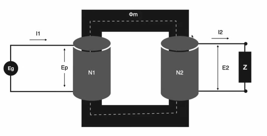
To understand CT operation clearly, it is helpful to study a regular transformer first. A power transformer has two windings. The primary winding receives supply. The secondary winding connects to a load. When supply is applied, current flows in the primary.
This current creates magnetomotive force. Due to this force, magnetic flux forms in the core. This flux links with the secondary. Because of this linking, voltage appears in the secondary. Once a load is connected, secondary current starts flowing. This is the basic transformer action.
Now, something important happens when secondary current flows. It produces its own magnetic field. This field opposes the primary field. As a result, the net flux in the core remains limited. This balance is essential. Without it, voltage would become unstable.
Also, in a power transformer, primary current depends on secondary current. When load increases, secondary current increases. Primary current also rises. When load reduces, both currents fall. This dependency is very important in power transformers.
Flux Interaction and Magnetic Balance in Transformers
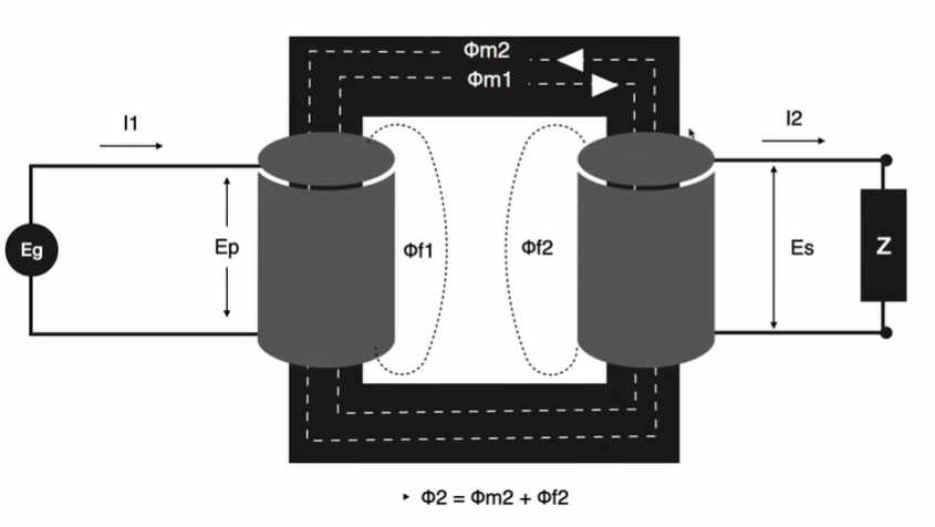
When both primary and secondary currents flow, each produces its own magnetomotive force. Each force creates its own flux. Primary current produces primary flux. Secondary current produces secondary flux. These fluxes move in opposite directions.
Each flux has two parts:
- Mutual flux, which links both windings
- Leakage flux, which escapes into air
Because mutual fluxes oppose each other, they cancel partially. The remaining part is called net flux. This net flux is responsible for secondary voltage. It stays nearly constant during operation. Because of this balance, transformer performance remains stable. If this balance is disturbed, voltage changes rapidly. This can damage insulation and equipment.
Power Balance and Current Relationship in Transformers
Another important concept is power balance. In a transformer, input power and output power remain almost equal. Losses are small in good designs. For example, if 10 kVA enters the primary, nearly 10 kVA appears at the secondary. If voltage reduces, current must increase. This keeps power constant.
This rule applies to power transformers. It also applies to current transformers. However, the way current behaves in CTs is different. This difference creates unique operating conditions.
Construction Difference Between Power Transformer and Current Transformer
Although CTs follow the same basic law, their construction is different. A power transformer has two windings. One is primary. The other is secondary. A current transformer usually has only one dedicated winding. This is the secondary winding. The primary is not a coil. Instead, it is the system conductor itself.
The conductor passes through the CT core. It acts as a single-turn primary. Sometimes, it may have two or three turns. However, most often, it has only one turn. Because of this design, CTs are compact. They also fit easily in switchgear and substations. This structure also affects how current behaves in CTs.
Series Connection Concept in Current Transformers
Current transformers are always connected in series with the power circuit. This means full line current flows through them. Because of this connection, CTs are also called series transformers. When current flows in the transmission line, it must pass through the CT. Therefore, primary current never stops while the circuit is energized.
This is different from power transformers. In power transformers, primary current depends on secondary load. In CTs, primary current depends only on system conditions. Even if nothing is connected to the secondary, primary current continues flowing. This feature plays a major role in CT safety.
Primary and Secondary Behavior in Current Transformers
In a CT, the primary side behaves differently from a power transformer. The primary is just a conductor. It carries system current. This current depends on load and faults. The CT cannot control it.
The secondary winding has many turns. Because of this, voltage is induced easily. This voltage drives current through meters and relays.
Standard secondary values are:
- 1 A
- 5 A
These values are safe for instruments.
When secondary current flows, it produces opposing flux. This keeps net flux low. As long as secondary current exists, magnetic balance remains. During normal operation, this balance ensures stable voltage. It also protects insulation. However, if secondary current stops, balance breaks. This creates dangerous conditions.
Practical Example: Normal Operating Condition of a CT
Consider a CT installed on a 36 kV transmission line. The line carries 1,000 A current. The CT has one primary turn. It has 1,000 secondary turns.
Because of this ratio, secondary current becomes 1 A. Now, assume a meter with 2 ohms resistance is connected. The voltage across the meter becomes:
1 A × 2 ohms = 2 V
This voltage is safe. Insulation remains protected. Flux remains balanced. This is a normal operating condition. No danger exists in this situation.
Practical Example: Open-Circuited Secondary Condition
Now, consider another situation. Suppose the meter is removed. The secondary becomes open. No current flows in the secondary. Because of this, no opposing flux is produced. Only primary flux remains in the core.
As a result, net flux increases sharply. The core moves toward saturation. Due to high flux, secondary voltage rises rapidly. Using transformation ratio, this voltage can reach thousands of volts. In some cases, it may reach tens of kilovolts.
Such voltage causes serious problems:
- Insulation breakdown
- Fire risk
- Equipment failure
- Danger to human life
Therefore, CT secondary must never remain open. When no load is connected, technicians must short the terminals. This allows current to flow. It also maintains flux balance. This rule is written clearly on CT nameplates.
Why Primary and Secondary Current Are Independent in CTs
In power transformers, primary current depends on secondary current. This creates automatic balance. In current transformers, this relationship does not exist.
Because CTs are in series, primary current flows continuously. It does not depend on secondary conditions. Load changes in the secondary do not affect it. This independence is useful for measurement. It ensures accurate sensing. However, it also creates risk.
If secondary current stops, nothing limits flux. Voltage rises dangerously. This is the main reason CTs require careful handling.
Key Differences Between Power Transformers and Current Transformers
The main differences can be summarized as follows:
- Power transformers transfer power. CTs measure current.
- Power transformers have two windings. CTs usually have one winding.
- Power transformer current depends on load. CT current does not.
- Power transformers can operate open-circuit. CTs cannot.
- CTs must always have closed secondary circuits.
Understanding these differences helps avoid mistakes in operation.
Summary of Working Principle of Current Transformer
A current transformer works on Faraday’s Law. Primary current creates magnetic flux. This flux induces voltage in the secondary. Secondary current produces opposing flux. This keeps net flux low. Balance remains stable during normal operation.
CTs are connected in series. Primary current flows continuously. Secondary current does not control it. Because of this design, CT secondary must never remain open. Open circuits create dangerous voltages. Practical examples clearly show how CTs measure high current safely.
Conclusion
The working principle of current transformers is simple in theory. However, it is critical in practice. It depends on electromagnetic induction, series connection, and magnetic balance. Primary current always flows. Secondary current maintains safety. Any interruption in this balance creates risk.
Understanding the difference between power transformers and CTs is essential for engineers. It also helps prevent accidents in substations. To gain deeper clarity and visual understanding, watching the original video is highly recommended.
