
What Are the Components of Ring Main Unit (RMU)? A Complete Explanation
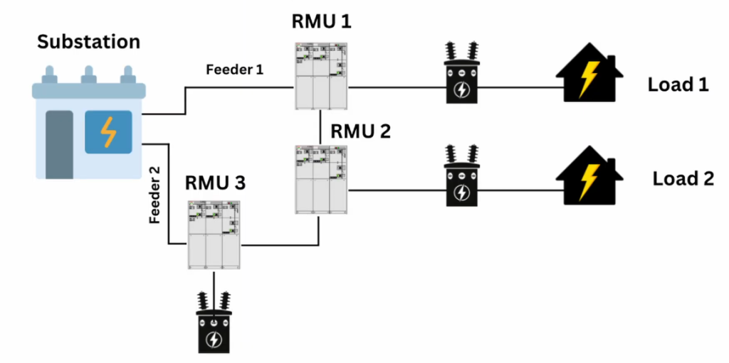
What Are the Components of Ring Main Unit (RMU)? A Complete Explanation https://www.theelectricalguy.in/wp-content/uploads/2026/01/maxresdefault-5-1024x576.jpg 1024 576 Gaurav Joshi https://secure.gravatar.com/avatar/f6a3006f3f7233a71d79d0e705c167ae12516870e5239627478665ae377435b3?s=96&d=mm&r=gRing Main Units form the backbone of ring main distribution systems. Without them, this system cannot operate. RMUs help control power flow, isolate faulty sections, and protect equipment. They ensure reliability in medium voltage networks. This article explains the components of Ring Main Unit (RMU) by following the exact flow of the referenced video. The explanation moves from concept to construction in a logical manner.
To understand the components clearly, it is important to begin with the basic single line diagram.
Table of Contents
- Single Line Diagram of Ring Main Unit (RMU)
- Three-Position Switch Disconnector in RMU
- Incoming and Outgoing Ring Feeders in RMU
- Transformer Feeder Arrangement in RMU
- Protection Using Current Transformer in RMU
- Gas Insulated Ring Main Unit Construction
- Cable Compartment in Ring Main Unit (RMU)
- Bushings in Ring Main Unit (RMU)
- Switch Disconnectors as Physical Components
- Switch Disconnector with Fuse for Transformer Protection
- HRC Fuse Assembly in RMU
- Low Voltage Compartment in Ring Main Unit (RMU)
- Voltage Detection Indicating System (VDIS)
- Pressurised Gas System in RMU
- Pressure Relief Arrangement in Ring Main Unit (RMU)
- Metal Enclosure of Ring Main Unit (RMU)
- Busbar System and Extensibility in RMU
- Circuit Breaker Module in Ring Main Unit (RMU)
- Circuit Breaker Operating Mechanism
- Summary of Components of Ring Main Unit (RMU)
Single Line Diagram of Ring Main Unit (RMU)
A Ring Main Unit can perform multiple functions. The number of functions depends on system requirements. Some RMUs have a single function, while others may have two, three, or more. A common configuration includes three functions.
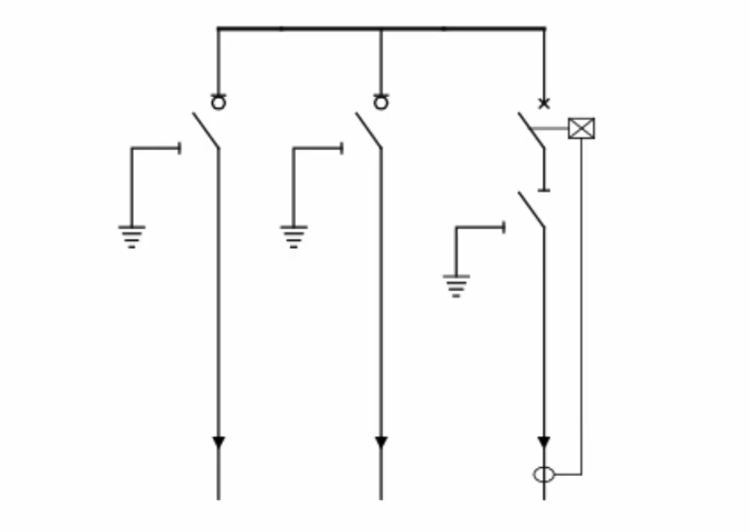
In the single line diagram, cables enter or exit the RMU from the bottom. From there, these cables connect to switching devices. Typically, the diagram shows two ring feeders and one transformer feeder. As a result, this layout helps maintain supply continuity in a ring network.
The single line diagram does not show physical parts. Instead, it explains how different functions connect electrically. Once this connection is clear, understanding the actual components becomes easier.
Three-Position Switch Disconnector in RMU
The ring feeders connect to three-position switch disconnectors. Each switch operates in three positions: closed, open, and earth. This design improves operational safety and flexibility.
A switch disconnector can interrupt normal rated current. It cannot interrupt short-circuit current. This capability differentiates it from a disconnector. A disconnector cannot interrupt any current and operates only under no-load conditions.
This distinction matters because RMUs rely on switch disconnectors for normal switching operations.
Incoming and Outgoing Ring Feeders in RMU
The incoming supply connects to the first switch disconnector. This feeder forms part of the ring main network. Power flows through this section into the RMU.
The second switch disconnector feeds power to another substation or load. From here, the cable exits the RMU. Together, these two feeders maintain continuity in the ring system. They also allow isolation when required.
Transformer Feeder Arrangement in RMU
The third function usually feeds a transformer. This feeder uses a circuit breaker instead of a switch disconnector. The circuit breaker provides reliable protection during fault conditions.
A three-position disconnector is installed in series with the circuit breaker. This disconnector allows safe isolation during maintenance. It does not interrupt current.
A small circle symbol identifies a switch disconnector. A disconnector does not have this marking.
Protection Using Current Transformer in RMU
A current transformer connects to the transformer feeder. It senses abnormal current conditions. The output of the current transformer connects directly to the circuit breaker trip coil.
When a fault occurs, the breaker trips immediately. This action isolates the faulty section. It protects the transformer and connected loads. With this, the basic single line diagram explanation is complete.
The next step is to connect this diagram to the actual physical components.
Gas Insulated Ring Main Unit Construction
In a gas insulated RMU, all switching devices are placed inside a sealed metal tank. In this design, the tank contains pressurised gas, commonly SF₆. This gas, in turn, provides insulation and supports arc interruption.
At the same time, copper busbars interconnect all functions shown in the single line diagram. Although the tank design may vary between manufacturers, the basic principle remains the same. In simple terms, a sealed enclosure houses all switching components under pressurised conditions.
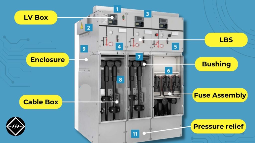
Cable Compartment in Ring Main Unit (RMU)
The cable compartment allows incoming and outgoing cables to connect to the RMU. This section is one of the most critical parts of the equipment. RMUs support different cable entry types such as front, bottom, rear, or side entry.
Each feeder has its own cable termination area. Poor cable joints can create hotspots. These hotspots may damage insulation and cause internal arc faults. This makes cable termination quality extremely important.
Bushings in Ring Main Unit (RMU)
Cables cannot connect directly to switching components. Bushings act as the interface between cables and internal equipment. They provide electrical insulation and mechanical support.
Bushings remain covered with insulation and may not be visible externally. Different bushing types exist, including short bushings, long bushings, and outer cone designs. Regardless of type, their role remains the same. They ensure safe and reliable connections.
Switch Disconnectors as Physical Components
After passing through the bushings, cables connect to switch disconnectors. These switches physically represent the ring feeders shown in the single line diagram.
One switch handles the incoming feeder. Another handles the outgoing feeder. Their three-position operation supports normal switching and safe earthing. This arrangement ensures reliable power flow through the RMU.
Switch Disconnector with Fuse for Transformer Protection
Some RMUs use a switch disconnector with fuse instead of a circuit breaker. This arrangement protects the transformer during abnormal conditions.
This solution costs less than a circuit breaker. However, it requires fuse replacement after every operation. This increases maintenance effort and reduces reliability compared to circuit breakers.
HRC Fuse Assembly in RMU
The high rupture capacity fuse assembly sits below the transformer feeder section. These fuses interrupt fault currents and protect the transformer.
When a fault occurs, the fuse blows and isolates the transformer. Maintenance personnel must replace the fuse before restoring supply. Although effective, this process is time-consuming and less reliable.
Low Voltage Compartment in Ring Main Unit (RMU)
The low voltage compartment is located at the top of the RMU. It houses all control wiring and low voltage devices. This separation improves safety and organisation.
This compartment includes:
- Earth fault indicators
- Voltage and current indicators
- Relays, when required
It also contains the Voltage Detection Indicating System.
Voltage Detection Indicating System (VDIS)
The Voltage Detection Indicating System shows whether voltage is present. It acts as a safety indicator for operators. If the system shows voltage presence, maintenance should not proceed.
This indication helps prevent accidents. It plays a crucial role in safe RMU operation.
Pressurised Gas System in RMU
Gas insulated RMUs operate under pressurised conditions. As a result, the sealed tank maintains insulation strength throughout operation. However, during abnormal conditions, internal faults may increase pressure inside the enclosure. In such cases, uncontrolled pressure can pose serious risks. Therefore, to handle this situation safely, RMUs include dedicated pressure control features.
Pressure Relief Arrangement in Ring Main Unit (RMU)
A pressure relief arrangement is provided, usually at the bottom of the RMU. It activates when internal pressure exceeds a defined limit.
This device releases pressure in a controlled manner. It protects the equipment and personnel working nearby. This feature forms a vital safety element in RMU design.
Metal Enclosure of Ring Main Unit (RMU)
All components are housed within a metal enclosure. This enclosure supports internal assemblies and protects them from external conditions.
It provides the required IP rating. It may also provide IK rating for mechanical protection. Without this enclosure, safe operation would not be possible.
Busbar System and Extensibility in RMU
Busbars connect the switching components. They also allow future expansion of the RMU. This feature is known as extensibility.
By removing a cover, additional panels can be added. These may include:
- Additional switches
- Circuit breakers
- Metering devices
RMUs with this feature support future network growth.
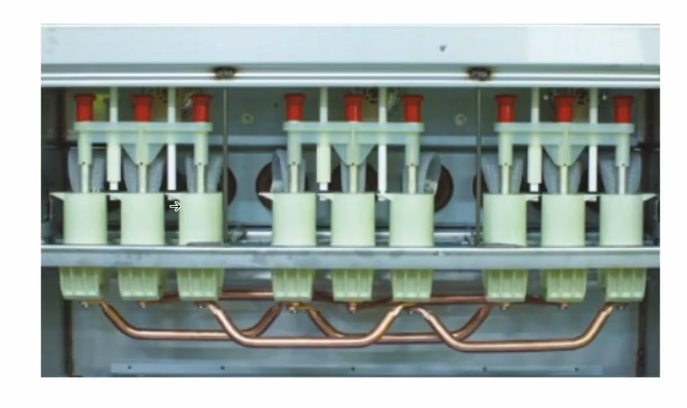
Circuit Breaker Module in Ring Main Unit (RMU)
Some RMUs include a dedicated circuit breaker module. These breakers typically use vacuum interrupters. Three vacuum bottles serve the three phases.
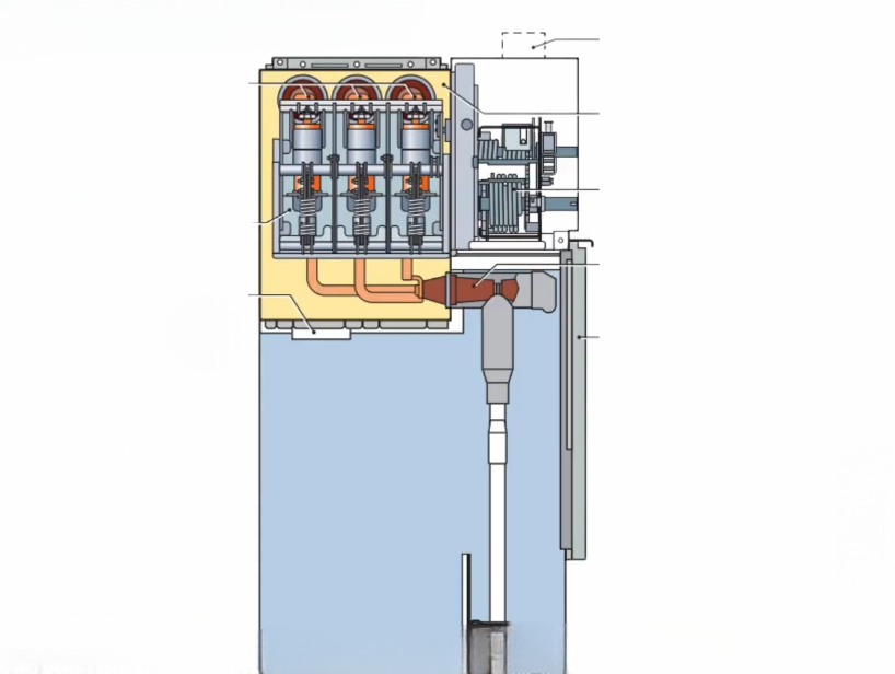
Cables connect through outer cone bushings. Busbars link these bushings to the vacuum interrupters. The breaker assembly remains enclosed within a sealed gas-filled tank.
Circuit Breaker Operating Mechanism
The circuit breaker operates using a spring-based mechanism. This mechanism controls opening and closing actions. It ensures fast response during fault conditions.
This design improves protection reliability. It also reduces maintenance requirements.
Summary of Components of Ring Main Unit (RMU)
The cable compartment allows safe cable entry. Bushings connect cables to internal equipment. Switch disconnectors manage ring feeders. Disconnectors support isolation. Circuit breakers and fuses protect transformers. The low voltage compartment houses controls and indicators. Gas tanks provide insulation. Pressure relief devices enhance safety. Metal enclosures provide protection. Busbars allow future expansion.
Each component performs a defined role. Together, they ensure reliable and safe RMU operation.
Conclusion
Understanding the components of Ring Main Unit (RMU) becomes easier when the single line diagram connects clearly to physical construction. Each part supports safety, continuity, and protection. For a clearer visual explanation and better understanding, it is recommended to watch the referenced video along with this article.
