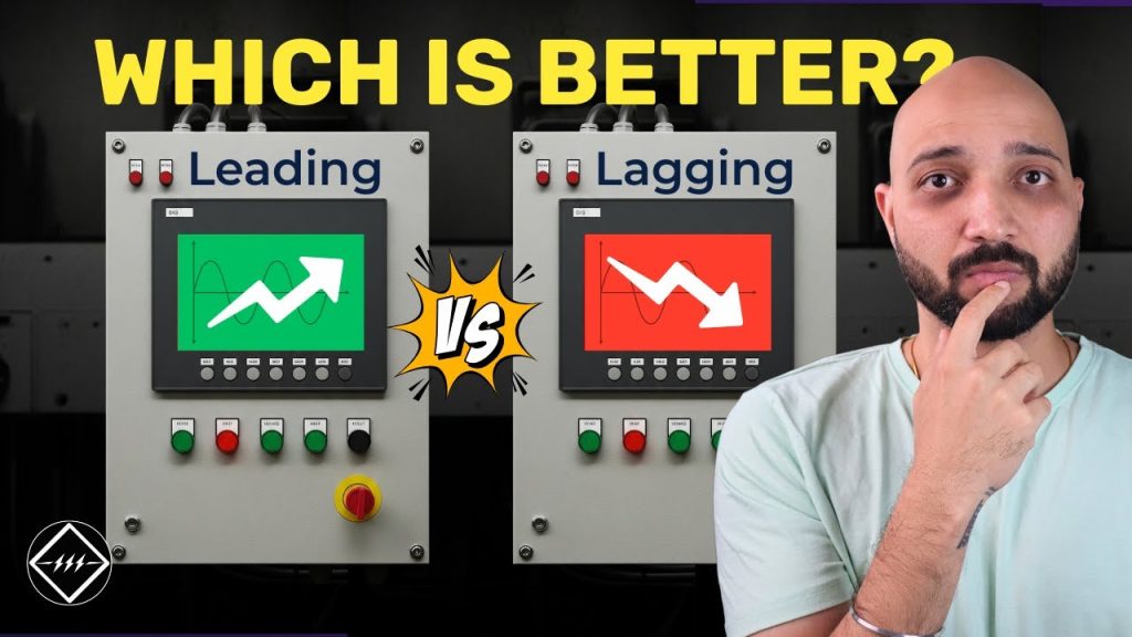
Leading vs Lagging Power Factor
Leading vs Lagging Power Factor https://www.theelectricalguy.in/wp-content/uploads/2025/09/maxresdefault-3-1024x576.jpg 1024 576 Gaurav Joshi Gaurav Joshi https://secure.gravatar.com/avatar/f6a3006f3f7233a71d79d0e705c167ae12516870e5239627478665ae377435b3?s=96&d=mm&r=gThe type of power factor decides if your system is consuming reactive power from the grid or delivering it back. To understand this better, we will look at three types of power factor: unity power factor, lagging power factor, and leading power factor.
Before we explore them, it helps to know the universal language of the electrical industry, the single line diagram. If you ever struggled to read or interpret one, understanding power factor will make those diagrams much clearer.
Table of Contents
- Understanding Power Factor
- Unity Power Factor
- Lagging Power Factor
- Leading Power Factor
- Comparing Leading vs Lagging Power Factor
- Conclusion
Understanding Power Factor
Power factor tells you how much of the total apparent power is active power. Modern systems consume apparent power because loads are different. We have resistive loads and inductive loads. Power factor measures the ratio of active power to apparent power. It helps us know how efficiently power is used.
Unity Power Factor
What is Unity Power Factor
A unity power factor exists in a purely resistive circuit. Imagine a 230 V, 50 Hz AC supply connected to a 60 Ω resistive load. There are no inductive or capacitive elements.
Waveform at Unity Power Factor
The voltage and current waveforms are perfectly in phase. Both reach their positive and negative peaks at the same time. They also cross zero together. This happens only in purely resistive circuits.
Why Unity Power Factor is Ideal
In this case, active power equals apparent power. Reactive power is zero. You can calculate active power using I²R, which gives 181 W. With no reactance, impedance equals resistance. The apparent power is identical to the active power. The power factor is unity.
Power Triangle for Unity Power Factor
The power triangle is a straight line. The line shows the active power of 181 W. Since reactive power is zero, apparent power overlaps active power. This is an ideal case, but industries rarely have purely resistive loads.
Lagging Power Factor
What is Lagging Power Factor
Most industries have mixed loads. They use resistive loads like lights and inductive loads like motors and transformers. Inductive loads contain coils or windings.
Waveform at Lagging Power Factor
When you add inductive loads, the voltage leads the current.
Current lags the voltage by an angle. In a purely inductive circuit, the lag can be 90°. In practice, resistance and capacitance reduce this angle. The waveforms are out of phase. Peaks and zero crossings do not match.
Power Calculations for Lagging Power Factor
In this case, active power is 515 W. Reactive power is 413 VAR. Apparent power becomes 671 VA. Apparent power is higher because of the reactive component. The power factor is 0.768 lagging. Positive reactive power means the circuit consumes reactive power from the grid.
Why Current Lags Voltage
Inductors oppose changes in current. This causes the current to lag the voltage.
This is the most common power factor in industries. To improve power factor, capacitors are added. They supply reactive power locally instead of drawing it from the grid.
Power Triangle for Lagging Power Factor
The power triangle has active power on the base and reactive power on the vertical side. Connecting these forms the apparent power.
Since reactive power is positive, the triangle extends upward. This indicates a lagging power factor.
Leading Power Factor
What is Leading Power Factor
Leading power factor appears in capacitive circuits. Consider a circuit with a 230 V, 50 Hz supply, a 50 Ω resistor, and a 100 μF capacitor.
Waveform at Leading Power Factor
Here, the current leads the voltage. Voltage lags by some angle. A purely capacitive circuit would show a 90° phase difference. Impurities like resistance affect the angle. The waveforms are out of phase but in the opposite way to an inductive circuit.
Power Calculations for Leading Power Factor
In this case, active power is 753 W. Reactive power is -479 VAR. Apparent power is 892 VA. The negative reactive power shows the system is delivering reactive power back to the grid.
The power factor is 0.844 leading.
Why Current Leads Voltage
In capacitive circuits, capacitors oppose changes in voltage. They adjust the current to maintain balance. This gives the current a head start. Voltage follows.
Rare Occurrence of Leading Power Factor
Leading power factor is rare. It happens when installed capacitors overpower the circuit. Capacitor banks are not loads. Loads consume power, while capacitors deliver reactive power. If capacitors overpower the system, inductors are added to balance it.
Power Triangle for Leading Power Factor
The power triangle for a leading power factor is the opposite of lagging. Active power is on the base. Reactive power, which is negative, is drawn downward.
Apparent power connects the two. This shows the system delivers power to the grid.
Comparing Leading vs Lagging Power Factor
Lagging power factor is most common in industries, especially because they use inductive loads. As a result, current lags behind voltage, and reactive power becomes positive. In this case, the system consumes reactive power from the grid.
On the other hand, leading power factor occurs in capacitive circuits. Here, current leads voltage, and reactive power turns negative. Consequently, the system delivers reactive power back to the grid.
Meanwhile, unity power factor is ideal but rare in real-world systems. It occurs only in purely resistive loads where, importantly, active and apparent power remain equal.
Conclusion
Leading vs lagging power factor explains how power flows in electrical systems. Unity power factor is ideal but uncommon. Lagging power factor dominates industrial settings. Leading power factor is rare and happens when capacitors overpower the load. For a better visual understanding of this topic, watch the video.

- Posted In:
- Power System
Gaurav Joshi
Gaurav, also known as TheElectricalGuy, is an accomplished electrical engineer with over 8 years of experience in the high and medium voltage switchgear industry. In addition to his professional endeavors, Gaurav has made significant contributions to the global electrical engineering community through his highly successful YouTube Channel. With over 240K subscribers and a prestigious silver play button from YouTube, he has become a trusted resource for electrical engineers worldwide. Gaurav's dedication to sharing knowledge extends to the creation of comprehensive courses, which have already attracted over 5000 students eager to enhance their skills in the field.
All stories by: Gaurav Joshi

