
Skin Effect – Definition, Causes, Effects, and Solutions
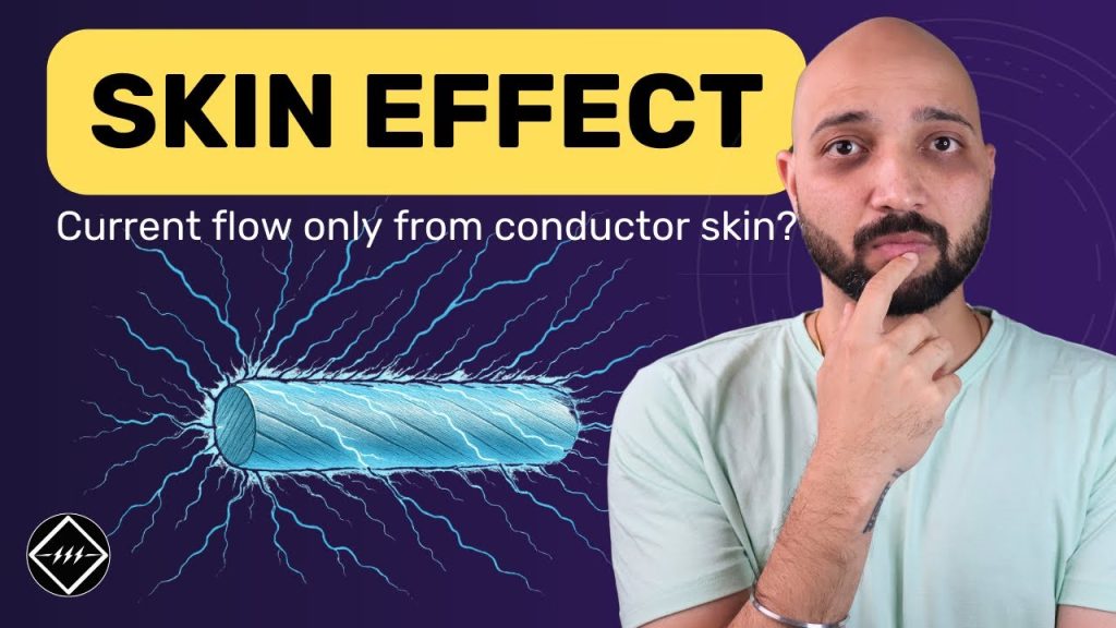
Skin Effect – Definition, Causes, Effects, and Solutions https://www.theelectricalguy.in/wp-content/uploads/2025/08/maxresdefault-2-1024x576.jpg 1024 576 Gaurav Joshi https://secure.gravatar.com/avatar/f6a3006f3f7233a71d79d0e705c167ae12516870e5239627478665ae377435b3?s=96&d=mm&r=gSkin effect is a key concept in electrical engineering especially in the power transmission field. It affects how alternating current (AC) flows through conductors. In a conductor carrying AC, the current does not spread evenly. It gathers near the surface instead of filling the whole area. This reduces the effective area for current flow, increases resistance, and leads to power loss.
Understanding this effect is crucial for power transmission. Over long distances, the effect can cause major energy loss. Let’s explore, why it occurs, its impact, and how to reduce it.
Table of Contents
- What Is Skin Effect?
- Why Skin Effect Occurs
- Why Current Stays Near the Surface
- Problems Caused by Skin Effect
- Factors Affecting Skin Effect
- How to Reduce Skin Effect
- Key Points About Skin Effect
- Conclusion
What Is Skin Effect?
Think of a large house where you live only on the balcony. Most of the space is wasted. In the same way, current in skin effect stays near the surface.

In a conductor carrying AC, the current does not spread evenly. Instead, it gathers near the surface, called the “skin.” The inner part remains underutilized. This uneven flow increases resistance and reduces efficiency.
Why Skin Effect Occurs
To understand skin effect, we need to recall some basics of electricity and magnetism.
Magnetic Field Creation
A conductor carrying current produces a magnetic field around it. With direct current (DC), the flow is steady, and the magnetic field stays the same. As a result, DC creates no problems.
Alternating Current and Changing Fields
With AC, the current changes direction and magnitude continuously. The magnetic field also changes in the same way.
Induced EMF and Opposition to Current

Faraday’s Law says that a changing magnetic field produces an electromotive force (EMF) in the conductor. This induced EMF opposes the change in current. This opposition is known as inductive reactance.
Why Current Stays Near the Surface
Let’s take a closer look at the conductor’s structure.
Layers in a Conductor
Think of the conductor as made up of many thin layers from the center outward. Each layer carries current and creates its own magnetic field.
Stronger Opposition in the Center
The layers near the center face magnetic fields from all surrounding layers. This increases the induced EMF and opposition to current flow there.
Less Opposition at the Surface
The surface layers have fewer surrounding layers to induce EMF into them. This means less opposition to current flow at the surface.
Path of Least Resistance

Like water flowing downhill, current chooses the path with the least opposition. In AC systems, that path is near the surface of the conductor. This is why the current density is highest at the outer surface.
Problems Caused by Skin Effect
Skin effect can create several issues in power systems.
Increased Resistance
Since only part of the conductor carries current, the usable cross-section becomes smaller. This makes the resistance higher.
Higher Power Losses
Higher resistance increases I²R losses. These losses grow with current and can become significant over long distances.
Lower Efficiency
More losses mean lower transmission efficiency. This wastes energy and raises operating costs.
Poor Voltage Regulation
Skin effect increases the impedance of transmission lines. This leads to a bigger difference between the voltage sent and the voltage received.
Factors Affecting Skin Effect
Skin effect depends on several factors that determine how current flows in conductors.
Frequency of Current
Inductive reactance is proportional to frequency. Higher frequency means stronger opposition and more noticeable. For example, it is more pronounced in 60 Hz systems than in 50 Hz systems.
Mathematical Expression – Skin Depth (δ):
Skin depth is the distance from the conductor’s surface where current density drops to about 37% of its surface value. It is given by:

Conductor Material
Materials with high magnetic permeability, like iron, have stronger skin effect. These materials let magnetic fields pass through, which is not ideal. But copper and aluminum have lower permeability, so they are better choices.
Size of the Conductor
Larger diameter conductors have more pronounced effect. This is because the inner layers are further from the surface and face more induced EMF.
How to Reduce Skin Effect
There are practical ways to minimize skin effect in electrical systems.
Use DC Transmission
In direct current, the frequency is zero. This means no changing magnetic fields and no skin effect. This is why HVDC transmission is gaining popularity for long distances.
Choose the Right Material
Using low-permeability materials like copper or aluminum helps. Copper is a good conductor, but it is expensive and can get stolen. Aluminum is cheaper, lighter, and widely used in transmission lines.
Use Stranded Conductors

Solid conductors suffer more from skin effect. Stranded conductors, such as Aluminum Conductor Steel Reinforced (ACSR), reduce it. These are made by bundling many small wires together, each carrying part of the current.
Use Hollow Conductors in Busbars
In substations, engineers prefer hollow tubes over solid busbars. This is because current flows on the surface; therefore, the empty center does not reduce performance.
Summary Table
| Factor | Influence on Skin Effect |
| Frequency | Higher frequency → more skin effect |
| Conductor Material | Higher permeability → more skin effect |
| Conductor Size | Larger diameter → more skin effect |
| Type of Current | AC → skin effect present, DC → no skin effect |
Conclusion
Skin effect is an important concept in electrical engineering. It explains why AC current flows mainly on the surface of a conductor. This leads to higher resistance and more power loss. Consequently, efficiency falls, especially during long-distance transmission.
By understanding the causes and factors affecting, engineers can choose materials and designs that reduce its impact. Techniques like using aluminum conductors, stranded wires, or even switching to HVDC can help.
For a clear visual explanation, watch the video. It shows the concept step by step and will make your understanding even stronger.
